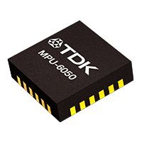
3D rendering of the MPU6050 MEMS motion sensor
The MPU6050 is a micro-electro-mechanical system (MEMS) device designed for motion tracking. It integrates a 3-axis gyroscope and a 3-axis accelerometer. These two sensing components are co-located on the same silicon die, sharing a common MEMS substrate, which is important for accurate sensor fusion. The device also incorporates a Digital Motion Processor (DMP) on-chip, designed to offload complex calculations. The MPU6050 comes in a small 4x4x0.9 mm Quad Flat No-lead (QFN) package. This compact form factor, coupled with integrated functionality, makes it ideal for space-constrained and power-sensitive applications such as wearables and mobile devices. The MPU6050 primarily communicates through an I2C interface, allowing for straightforward integration into most microcontroller-based systems. It’s essentially a one-stop shop for getting crucial orientation and motion data. This article will provide more detailed information from the MPU6050 datasheet.Overall Key Sensor Specifications
- Full-scale range (FS_SEL / AFS_SEL) — The maximum measurable ± angular rate (°/s) for the gyroscope or ± acceleration (g) for the accelerometer selected by a configuration bit.
- ADC word length — Number of digital bits produced by the on‑chip analog‑to‑digital converters.
MPU6050 Datasheet Pinout
The MPU6050 offers pins for power, communication, and auxiliary functions.
Let’s go through some of the most important pins:
- VDD (Pin 13): This is your power supply for the analog and digital sections of the device. It typically operates between 2.375V and 3.46V.
- GND (Pin 18): The common ground reference for the device.
- SCL (Pin 23) and SDA (Pin 24): These are the I2C serial clock and serial data lines, respectively. These two pins are your primary communication conduit for data transfer and configuration.
- AD0 (Pin 9): This pin allows you to select the least significant bit (LSB) of the I2C peripheral address. By pulling it high or low, you can connect two MPU6050s to the same I2C bus, each with a unique address (0x68 or 0x69).
- INT (Pin 12): The interrupt output pin, signaling when an event, such as a data-ready condition or motion detection, has occurred.
- FSYNC (Pin 11): This is a frame synchronization input pin, useful for accurately timing data acquisition, especially in multi-sensor systems.
- AUX_DA (Pin 6) and AUX_CL (Pin 7): These are the auxiliary I2C serial data and clock lines, respectively. The MPU6050 can act as a controller on this bus to interface with external sensors, such as a magnetometer.
Here’s a general pinout from the MPU6050 datasheet:
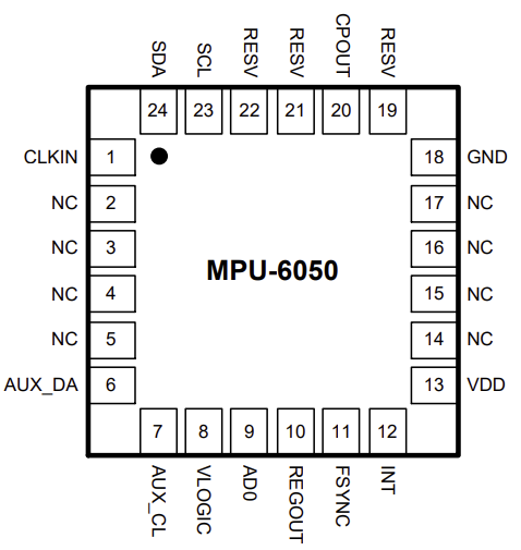
Pinout of the MPU6050
The Digital Motion Processor (DMP)
One of the standout features of the MPU6050 is its embedded Digital Motion Processor. The DMP is a miniature, specialized co-processor right there on the sensor chip. Its primary role is to offload demanding calculations and sensor fusion algorithms from your main microcontroller or CPU.
Why does this matter? Processing raw accelerometer and gyroscope data to accurately determine an object’s orientation in 3D space (often called sensor fusion) can be quite computationally intensive. The DMP brings several compelling advantages to the table:
- Offloads Host CPU: Without the DMP, your main processor would be burdened with floating-point math, quaternion calculations, and filter implementations, slowing down other critical tasks. The DMP handles all that heavy lifting internally, giving your main CPU more headroom for application-specific logic.
- Complex Algorithm Execution: The DMP can execute complex algorithms directly on-chip. This includes:
- Processing 6-axis motion fusion data to provide real-time orientation outputs (like quaternions or Euler angles).
- Gesture recognition.
- Even low-power functions such as pedometry (step counting).
- Simplified Firmware & Reduced Power: The microcontroller receives already-processed, ready-to-use data which simplifies firmware development and reduces the system’s overall power consumption, as the main CPU can remain in a low-power state more frequently.
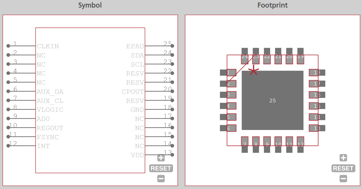
CAD data for the MPU6050 from Ultra Librarian
The Gyroscope: Detecting Angular Velocity
The MPU6050 incorporates three independent vibratory MEMS (Micro-Electro-Mechanical Systems) rate gyroscopes. If you’ve ever spun a top or watched a figure skater spin, you’ve witnessed angular velocity in action. These gyros are precisely engineered to detect rotation around the X, Y, and Z axes of the device.
How does it work? It leverages the Coriolis Effect. When the MPU6050 rotates, this effect causes a tiny, imperceptible vibration within the MEMS structure. This vibration is then detected by highly sensitive capacitive pickoffs, which convert the mechanical motion into an electrical signal. This signal, proportional to the angular rate, gets amplified, demodulated, and filtered locally on the chip.