

Using digital circuit simulation for circuit board testing
Designing and building electronic circuit boards is a complex process. For new product introduction (NPI) development, process efficiency rests on the optimization of the design⇒build ⇒test (DBT) cycle. By incorporating digital circuit simulation during design, you can minimize or eliminate common issues that increase the time and costs of the PCBA development cycle.
Choosing the best online digital simulator requires knowing what tools are available and how to select the one that best meets your needs.
Online Digital Circuit Simulator Options
The table below lists the top online digital circuit simulators according to functionality, capabilities, and usability.
|
TOP ONLINE DIGITAL CIRCUIT SIMULATORS |
|||
|
Rank |
Simulator Tool |
Functions and Capabilities |
Usability |
|
1. |
Full range of simulations, including complex analog signal and parametric measurements, Monte Carlo, thermal analysis, et. Access to a full library of TI component models. |
Free |
|
|
2. |
Comprehensive analog circuit simulation. Integrated schematic capture. |
Free |
|
|
3. |
AC and DC circuit simulation, primarily for students and educators. |
Free and license options. |
|
|
4. |
Simple AC and DC circuit simulation. Integrated with schematic capture, board layout, and component library creation capability. |
Limited capability free version and subscription options. |
|
|
5. |
Simple and easy-to-use open-source circuit simulator. Limited parts library. |
Free |
|
The list above is not exhaustive, but it includes some of the most popular online digital circuit simulators. Digital circuit simulation can be useful for any electronic circuit, irrespective of the types of signals transmitted, received, or processed. Additionally, simulation can be applied to each stage of development.
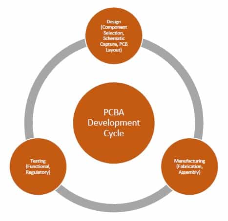

Stages of the PCBA development cycle
Each iteration, from design to manufacturing to testing, requires resources. Therefore, the objective is to optimize this process by achieving the desired quality design that meets functionality and regulatory testing requirements while minimizing the number of cycles needed. This is best accomplished by leveraging the power of online digital circuit simulation.
Digital Circuit Simulation Applications
- Design
During design, circuit simulation can be utilized to determine performance criteria, choose components, set layout parameters, and aid ECAD and MCAD collaboration.
- Manufacturing
Digital circuit models are used to validate manufacturability prior to board build. This includes checking that the clearances, drill hole parameters, footprint locations, solder masking, trace dimensions, and copper weights are all within acceptable limits.
- Testing
For functional testing, electrical parameters for various test points can be determined and then verified through physical testing methods.
As shown above, simulation can be a significant asset throughout the development process. Let’s delve a bit deeper into how it can improve your design process.
Using Circuit Simulation to Improve PCBA Design
Just as simulation can be utilized for all stages of PCBA development, it can also be applied to both primary design activities, schematic capture and board layout, as described below.
Schematic Capture
Creating your schematic consists of choosing the best components and utilizing accurate part symbols to generate and test your nets or interconnections. These basic requirements provide no information as to how your circuit will actually operate or perform. Of course, good use of datasheets will allow you to assume or estimate performance, however, it is highly likely that you will need many DBT cycles to maximize your design.
A better option is to employ digital simulation to preview your board’s operation before moving to layout and manufacturing. By applying simulation, you can refine your design by testing various components—such as BJT transistor models using Cadence’s PSpice simulation program for small signal analysis—sub-circuit architectures and routing schemes to optimize your design and specify testable performance criteria.
Board Layout
Once your design has been optimized schematically, then the PCB layout can be done with confidence. During board layout, simulation can be used to optimize component placement, trace routing, via type selection and location, layer stackup, solder masking, silkscreen fiducial placement, and other DFM compliance parameters to ensure your board is manufacturable. Again, the PSpice circuit simulator can be used to analyze the peak current flow of different models in order to optimize trace routes during layout design.
Applying simulation during the design phases, as described above, the likelihood that your board can be built the first time is greatly increased, while the number of iterations required to achieve a production-ready design are minimized, provided that you select the right online digital circuit simulator.
Choosing the Best Online Digital Circuit Simulator for Your Design
As shown in the previous sections, PSpice can be used in all aspects of PCBA design, enabling you to achieve a board design optimized for functionality and operation, as well manufacturability, prior to passing it to your CM. The success of your implementation of digital simulation depends upon how accurately your digital model matches with the physical embodiment of your board. Therefore, it is essential that you choose a digital circuit simulator that meets certain requirements, as listed below.
Guidelines for Digital Circuit Simulator Selection
- Ensure the simulator can read data in a format that your design tool can export.
Many simulation programs require input data in specific formats. It is best if your simulator can read data in a format that your design tool exports. If not, data conversion will be necessary, introducing an opportunity for error.
- Ensure that your program can read the exported data format from the simulator.
Similar to your simulator being able to directly read export data, your program should be able to import the simulator output directly. Otherwise, important information may be lost or misinterpreted in the translation.
- Choose a simulator that allows for design modifications.
Your simulator should allow you to test various models. If not, a great deal of back and forth may be required to hone in on the best design.
As shown above, data format matching is a critical element for simulation usage. The best way to ensure this synchronization is to use a PCB design software package with digital simulation functionality. PSpice and seamless component integration ensure the synchronization of data formats and yield the most accurate results. An example of this is Cadence’s OrCAD with Ultra Librarian integration built-in.
If you’re looking for a source of CAD models for common components that easily integrate into popular ECAD applications or your online digital circuit simulator, Ultra Librarian helps by compiling all your sourcing and CAD information in one place.
Working with Ultra Librarian sets up your team for success to ensure streamlined and error-free design, production, and sourcing. Register today for free.