Site icon Free Online PCB CAD Library

Electrolytic Capacitor Datasheet: Evaluation

Nichicon UCD1J221MNQ1MS electrolytic capacitor CAD models from UL

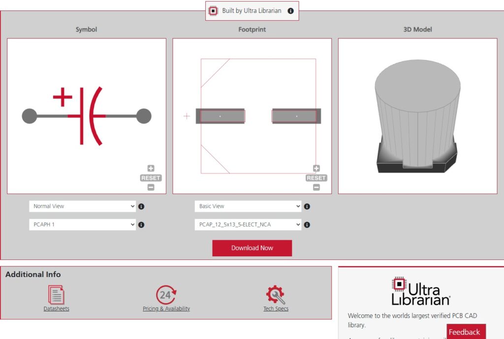
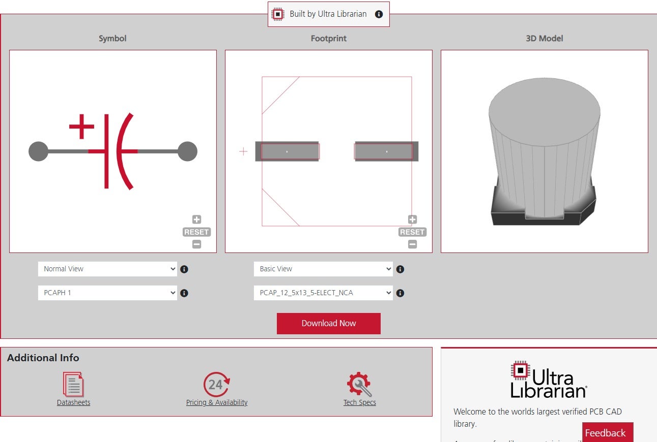
Symbol, footprint, and 3D CAD model of Nichicon UCD1J221MNQ1MS electrolytic capacitor

Electrolytic capacitors are polarized capacitors that use an electrolyte to achieve large capacitance values in a small package, making them ideal for filtering, coupling, and decoupling applications in power supplies and signal circuits. Unlike ceramic or film capacitors, these devices provide bulk capacitance economically, which is critical in smoothing voltage and handling ripple currents, and have the following key advantages:
Electrolytic Capacitors Key Advantages
Feature Description
High Capacitance per Volume Allows designers to manage low-frequency filtering with fewer components.
Polarity Sensitive Must be installed with correct polarity to avoid failure or explosion.
Voltage Ratings Available in a wide range but generally lower than some film alternatives for a given size.
ESR and Ripple Current Typically have higher ESR compared to ceramics, but this can aid damping in some designs.

Because of these characteristics, selecting the right electrolytic capacitor requires careful evaluation of datasheets to match your design’s objective voltage level, maximum ripple, ESR, operational lifetime, temperature requirements and satisfy industry standards

What to Look for in an Eletrolytic Capacitor Datasheet

When evaluating an electrolytic capacitor datasheet, focus on the following:

Important Electrolytic Capacitor Datasheet Information
Parameter Details
Capacitance and Tolerance • Nominal capacitance at rated conditions
• Typical tolerances are wide (±20%), impacting filter and timing circuits
Rated Voltage (WVDC) • Maximum DC voltage the capacitor can continuously withstand
• Design voltage should include derating (e.g., operate at 60–80% of WVDC for longevity)
Ripple Current Rating • Maximum AC ripple current without exceeding temperature rise limits
• Critical for power supplies where ripple can cause heating and shorten capacitor life
Equivalent Series Resistance (ESR) • Impacts ripple voltage and thermal behavior under AC load
• Lower ESR reduces ripple voltage but may lead to resonance issues in some circuits
Operating Temperature Range • Higher ratings (e.g., 105°C vs. 85°C) generally indicate longer life under high ripple and ambient heat
Load Life / Lifetime Expectancy • Specified as “2000 hours at 105°C” etc.
• Real-world lifetime increases significantly when operated at lower temperatures
Leakage Current • Important for low-power or timing-sensitive circuits
• Leakage influences charge/discharge behavior
Size and Package • Physical dimensions must match your PCB footprint and mechanical constraints

Datasheets should also provide dimensions for footprints and landing patterns, as shown below for the Nichicon UCD series of electrolytic capacitors.

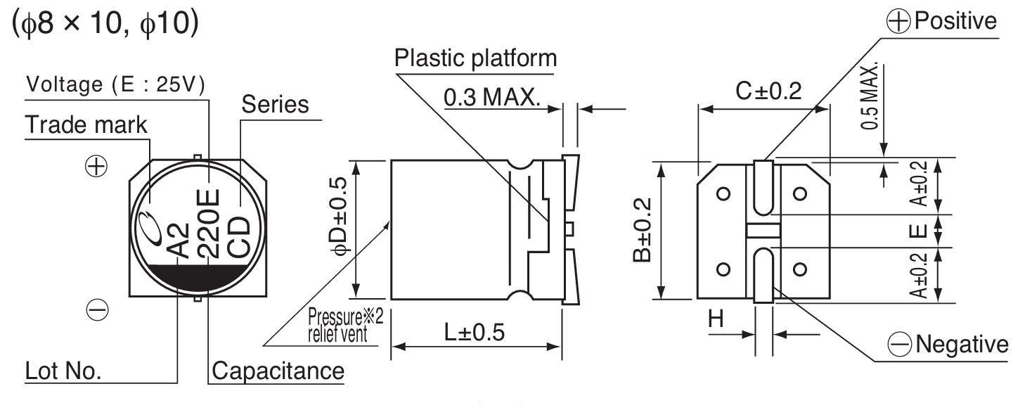
Dimensional details for accurate footprint and landing pattern layout for Nichicon UCD electrolytic capacitors (φ8×10, φ10) including diameter, length, tolerances, lead spacing, and polarity indicators

Evaluating Electrolytic Capacitor Datasheets

The Nichicon UCD series and Panasonic EEE-FC1A102P offer practical examples for learning how to interpret and evaluate an electrolytic capacitor datasheet. 

Nichicon UCD series Electrolytic Capacitor Datasheet

Known for its balance of compact size, high capacitance range, and temperature resilience, this series is frequently used in filtering, decoupling, and power supply circuits where ripple current handling and stability are critical. By understanding how to navigate this datasheet, you can confidently align these capacitors with your design’s performance and lifetime goals. 

At first glance, the datasheet can feel dense with numeric tables, but it follows a consistent structure:

  • General Characteristics: Category temperature range, voltage range (6.3V–100V), and capacitance range (1µF–3300µF).
  • Performance Metrics: ESR (via tan δ), leakage current, endurance ratings at 105°C, ripple current ratings, and frequency derating factors.
  • Mechanical Data: Dimensions for various case sizes, lead spacing, and maximum height—critical for PCB fit.

The datasheet also details endurance under load, shelf life characteristics, and temperature stability, allowing you to project how the capacitor will perform under real-world thermal and electrical stress.

Key Points for Practical Evaluation

When working with the Nichion UCD series, focus on:

Capacitance and Voltage Ratings: Capacitance up to 3300µF, with rated voltages up to 100V, covering typical filtering needs.
Operating Temperature Range: –55°C to +105°C, suitable for consumer and industrial applications requiring thermal resilience.
Ripple Current Handling: Ripple current ratings at 105°C, 100kHz, crucial for switching power supplies.
ESR (tan δ) and Impedance: Provided values assist in modeling ripple voltage in your power delivery network.
Mechanical Fit: Available in diameters from 4mm to 18mm and various lengths, allowing for flexibility in compact designs.
Lifetime Projections: Load life of 2000–5000 hours at 105°C, which increases substantially at lower operating temperatures, aiding in long-term reliability planning.

These metrics enable you to confirm whether the part will meet your circuit’s needs in terms of ripple tolerance, voltage stress, and physical layout.

Nichion UCD Electrolytic Capacitor Datasheet Key Parameters
Parameter Value / Range
Capacitance Range 1µF – 3300µF
Rated Voltage Range 6.3V – 100V
Category Temperature Range –55°C to +105°C
Capacitance Tolerance ±20% at 120Hz, 20°C
Leakage Current ≤ 0.01CV or 3µA (whichever is greater)
Ripple Current (105°C, 100kHz) Up to 1610mA depending on case size
tan δ (Dissipation Factor) 0.26 (6.3V) down to 0.07 (100V)
Endurance (Load Life) 2000–5000 hours at 105°C depending on size
Impedance Ratio (ZT/Z20) Max 4 at –55°C / +20°C
Case Sizes φ4×5.8mm up to φ18×16.5mm
Mounting Radial, with vibration-resistant variants available

Evaluating the Panasonic EEE-FC1A102P Electrolytic Capacitor Datasheet

The Panasonic EEE-FC1A102P is part of the FC Series of low-impedance, surface-mount aluminum electrolytic capacitors. This series is well-suited for power supply filtering and decoupling applications, offering a balance of compact size, high ripple current handling, and stable performance at elevated temperatures. By reviewing its datasheet, designers can align these capacitors with voltage, capacitance, and layout needs while ensuring thermal and electrical reliability.

The following table lists selected critical parameters, their extracted values for the EEE-FC1A102P, and where you can find them in the datasheet for quick reference during design evaluation:

Panasonic EEE-FC1A102P Electrolytic Capacitor Datasheet Key Parameters
Parameter Value Datasheet Location
Series FC Top header and markings table
Rated Voltage (V.DC) 10V Part number breakdown & table
Capacitance 1000µF Part number breakdown & table
Capacitance Tolerance ±20% (120 Hz, 20°C) Specifications section
Category Temperature Range –40°C to +105°C Specifications section
Endurance 1000 hours at 105°C Specifications section
Ripple Current (100kHz, 105°C) 670 mA RMS Table with case sizes
Impedance (100kHz, 20°C) 0.15 Ω Table with case sizes
tan δ (Dissipation Factor) 0.19 Table with case sizes
Leakage Current ≤ 0.01CV or 3µA (whichever greater) Specifications section
Case Size 10mm diameter × 10.2mm height Table with case sizes
Mounting Type Surface Mount (SMD) Top description & features
RoHS Compliance Yes Features section

If you’re looking for CAD models for common components or information on how to fully leverage the wealth of design information from your electrolytic capacitor, Ultra Librarian helps by compiling all your sourcing and CAD information in one place.

Working with Ultra Librarian sets up your team for success to ensure streamlined and error-free design, production, and sourcing. Register today for free.

Exit mobile version