One sentence-or-less description of image with a potential topic found in the blog
Far too often, it is incorrectly assumed that all you need to choose a capacitor is its voltage and current requirements. Another misconception is that exceeding a capacitor’s voltage rating will cause the device to fail. Knowing how to choose the right capacitor for your design requires understanding how these parts work and taking several design factors into account. Armed with this knowledge will ensure your circuit performs as desired and help you to avoid any unexpected operational failures once your board is deployed.
How to Choose the Right Capacitor
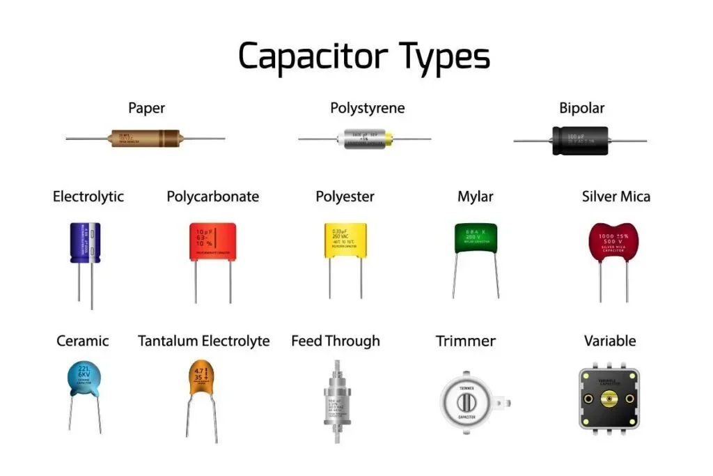
Capacitors are relatively simple passive electronic components. However, they perform several critical functions for electronic circuits. These functions include decoupling, filtering, power supply conversion, impedance matching, grounding efficiency, and minimizing electromagnetic interference (EMI). Although voltage and current ratings are important when choosing a capacitor, other factors will influence how capacitors will function in your circuit and should be considered as well.
Understanding and considering these factors can sometimes be critical to the success of your board build, installation, and operation.
Dielectric Properties
A capacitor is a passive element that temporarily stores electric charge from an internal electric field source before dissipating it through a load again. It consists of two metallic plates separated by a dielectric material, as shown below.
The capacitance can be calculated using the formula:
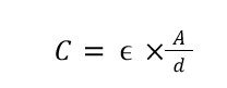
Where;
C= capacitance
𝞊 = dielectric permittivity
A= Plate area in sq meters
d= distance between plates in meters
Choosing capacitors with high dielectric strength offers high capacitance. The table below shows characteristics of common capacitor types, sorted by dielectric materials.
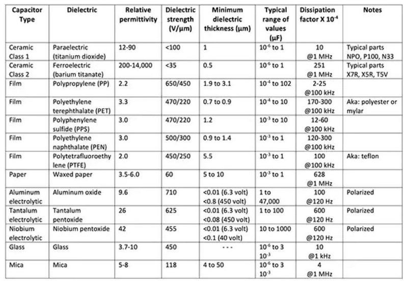
Table Source: Digikey Electronics
Temperature
Every capacitor has a specific operational temperature limit mentioned on the package. Beyond that temperature limit, the insulation around the dielectric starts to degrade and may cause electrolyte loss and leakage current. Here is a quick comparison of three popular types of capacitors based on their maximum operating temperature.
Selecting a capacitor that can safely operate under the maximum operating temperature of the application is always imperative.
Effective Series Resistance
Engineers are often surprised to learn that the equivalent circuit of a capacitor includes an effective serial resistance (ESR) and an effective serial inductance (ESL), as shown below. The internal resistance is due to the materials, design, and manufacturing process.
The value of ESR changes with a change in frequency, like a variable capacitor. At low frequency, the ESR value is very high and decreases with the increase in frequency. It also changes with the temperature change.
The mathematical expression is as follows:
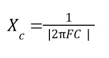
Here, XC represents the capacitive reactance, including ESR and ESL. The value is inversely proportional to the frequency of operation. Terms F and C represent frequency and capacitance, respectively.
That means, at high frequency, the capacitor offers the easiest path to the current flow. Thus, capacitors with low ESR values are always preferred. It is imperative to check the datasheet to confirm the best temperature and frequency combination to operate the capacitor at the lowest ESR value possible. Usually, the ESR of electrolytic capacitors is the highest, whereas that of film capacitors is the lowest.
Note: A same-rated capacitor but from two different manufacturers may have two different ESR values for all the same conditions.
Resonance
There is always a reduction in power of a signal when it travels through a capacitor. This is known as insertion loss. In an ideal capacitor, it increases with the increase in frequency. However, in an actual capacitor, the loss increases until the capacitor attains its self-resonance frequency (the frequency at which impedance becomes zero) and then decreases.
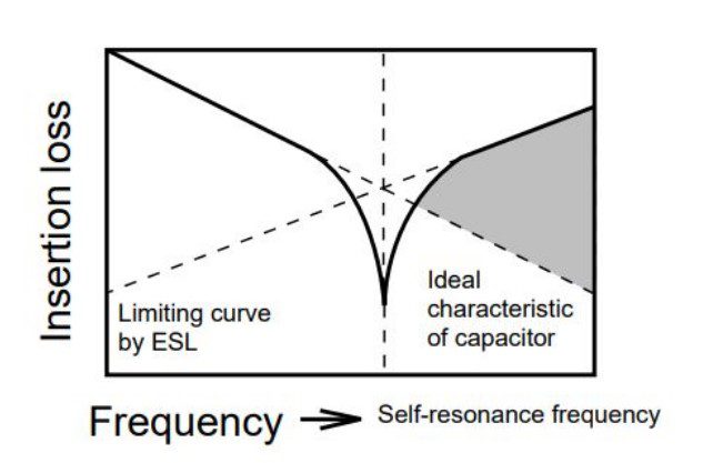
That being said, this concept is used to reduce the noise signal of a capacitor until it hits the self-resonant frequency. That’s why, in a high-frequency range, it is imperative to choose capacitors with a high self-resonance frequency (or low ESL value) for superior noise suppression.
Dissipation Factor
Now that we know capacitors have internal resistance, it is logical to witness some power loss when an AC voltage is applied. This rate of loss is known as the dissipation factor.
The mathematical expression is as follows:
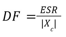
Here, DF represents the dissipation factor.
If you take the datasheet of any capacitor, you will notice that for a particular temperature and frequency of operation, the capacitor has different DF values at different stages of rated voltage. Consult your CM to help you select the best capacitor for your application with the lowest DF possible.
DC Biasing
The capacitance rating noted on a capacitor’s datasheet is under ideal conditions without any DC supply. However, if you are considering a ceramic capacitor with a high dielectric constant, under practical application scenarios, a small DC supply can change the capacitance value. That’s called DC biasing. Under such circumstances, you have three options:
Capacitor Selection Options With Significant DC Biasing Effect
- Go for a high capacitance value
- Use a physically larger package size
- Switch to a different type
Tolerance
The tolerance value represents the minimum and the maximum range of a capacitor from its nominal value. For example, a 1000µF capacitor with ±15% tolerance value can be used in 985µF – 1015µF applications. For sensitive applications such as timing elements, capacitors with a low tolerance are preferred. However, coupling capacitors have a wide tolerance to allow even the lowest frequencies with ease.
Polarization
Polarized capacitors (P-C) are used across the voltage in a certain polarity. The negative terminal has a negative symbol over the surface of the capacitor and has a smaller lid than the positive terminal. Aluminum electrolytic capacitors are polar capacitors and come with two lids of different lengths.
On the other hand, non-polar capacitors (N-P-C) can be connected either way in a circuit design. Ceramic capacitors, film capacitors, and electrolyte capacitors are non-polar.
P-Cs offer a large capacitance value in a tiny package. They also cost significantly less than N-P-Cs for the same capacitance and voltage ratings. However, a P-C has a large leakage current and can not operate at higher frequencies like an N-P-C can. While a P-C finds its major application in DC circuits, N-P-Cs can be used in both AC and DC, and at low or high frequencies.
The table below shows the types of capacitors and their area of application.


 compared to a traditional USB-A cord (right).")
")