


The CD0175B Quad Counter from Texas Instruments
Albert Einstein once said, “The only reason for time is so everything doesn’t happen at once.” So, it is worth wondering, does time exist naturally or is it something humans constructed? Regardless of whether time is just an illusion, the concept of time has been completely embraced by humanity at large.
Measuring time requires a means of counting from one moment to another, which is why we have clocks. In digital electronics circuits, clocks are also required to distinguish between pulses that define transmitted and/or received data and information. Counters, on the other hand, are used to store and display the number of times some circuit event has occurred. Although counters can be used in circuits displaying time, they do not measure time directly.
Let’s take a look at these important circuit components and delve into the operation of a common counter by examining the CD4017 datasheet.
Counter Circuits and Their Uses
Counters are widely used in digital electronic circuits. Most often, these devices are comprised of flip-flops that change state—output changes based upon the current state of the input—when a clock signal is applied. Typically, counters generate coded digital number outputs such as binary, binary-coded decimal (BCD), or gray code. The number size that a counter can represent is determined by its modulus, which corresponds to the number of flip-flops. For example, a modulus 4 counter has four flip-flops that each generate a single binary digit or bit output and the counter can represent up to 24 = 16 different numbers.
Counters may be synchronous, where all of the flip-flops are tied to the same clock and change state simultaneously, or asynchronous, where the flip-flops are cascaded and change state sequentially. Common counter types are listed below.
Common Types of Counters
- Synchronous
-
- Decade counter
- Up/down counter
- Modulus counter
- Ring counter
- Johnson counter
- Asynchronous
- Ripple counter
Counters may be included in processors, FPGAs, or other large, complex component modules. General-purpose counters are often packaged as separate ICs. As an example, the CD4017, which is discussed below, comes in PDIP, SOIC, SOC, and TSSOP standard packages.
The CD4017 Counter
The CD4017 is manufactured by Texas Instruments and comes in 16-pin IC packages. The counter IC module contains 4 CMOS D flip-flops that are independently accessible. However, flip-flop clocks and resets (clear) are all tied together for synchronous operation, as shown in the figure below, from the CD4017 datasheet.
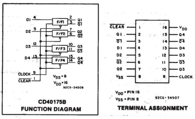

Diagram and pinout for the CD40175B
CD4017 Parameters
The operation of the CD4017 is simple and straightforward; however, the device is an active component, as are most counters—it requires an external power supply and is intended to be implemented in more complex circuits.
For this purpose, the following parameters are important:
| PARAMETER VALUES FOR THE CD4017 COUNTER | |
| Parameters | Maximum Values |
| DC Supply Voltage | -0.5V – 20V |
| Input Voltage Range | -0.5V + DC Supply Voltage +0.5V |
| DC Input Current | ±10mA |
| Power Dissipation (package) | 500mW |
| Power Dissipation (per output) | 100mW |
| Operating Temperature | -55°C – 125°C |
| Soldering Temperature | 285°C |
The range of values for the counter enables usage in a variety of circuit configurations. However, there are alternatives to the CD4017, including the NTE Electronics TTL74175. This quad counter can operate similarly to the CD4017, but at lower max voltage (7V) and current (1mA).
Using the CD4017 Datasheet
The CD4017 datasheet includes invaluable parametric data and graphics that are invaluable for component selection and proper utilization in circuit architectures. For this component, the datasheet is quite comprehensive and contains other important information such as the schematic symbol, footprint, and 3D model. These graphical elements are required to accurately design your PCBA; however, an actual CAD file format, as shown below, is needed for direct implementation.
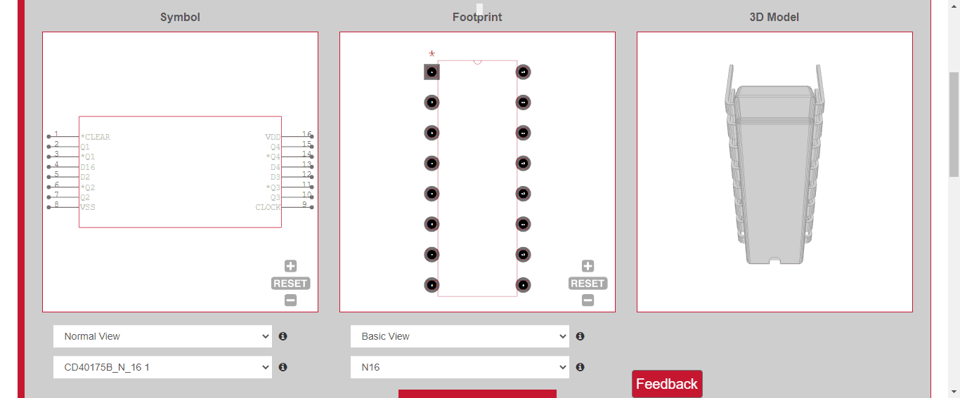

Symbol, footprint, and 3D model for CD40175B
The symbol, footprint, and 3D model above—which can be uploaded in many popular ECAD applications—is available from Ultra Librarian, the most comprehensive component database available.
If you’re looking for accurate CAD models and/or data and information for common components such as the general-purpose counter and CD4017 datasheet, Ultra Librarian can help by compiling all your sourcing and CAD information in one place.
Working with Ultra Librarian sets up your team for success to ensure any design is going through production and validation with accurate models and footprints to work from. Register today for free.