If you’ve worked with a component before and you’re very familiar with its specifications, you probably won’t need to read a datasheet. Whenever you’re comparing new components, or you need to know the limits of a new component, it’s critical that you scan through a datasheet to find the information you need. Some datasheets provide either far too much or far too little information. Whereas other documents ostensibly called “datasheets” are really technical briefs without sufficient information.
When you do find the datasheet you need for a new component, you may spend anywhere from minutes to hours learning important specification information. This is especially true if you need to create a footprint and 3D model from a datasheet. With the right component search service, you can cut down on the time you’ll spend studying datasheets and you can spend more time worrying about creating powerful PCBs for new products.
How to Read a Component Datasheet
The strategy for reading through a component datasheet depends on the type of component and the information you need to find. If you’re working with passives or ICs with standardized packaging, you’re probably less focused on footprints and more focused on electrical specifications.
A great datasheet will have the important electrical specifications you need summarized on the first page alongside packaging information. Some datasheets are nicely sectioned and include a clear table of contents, while others will cluster information into a datasheet with no clear organization.
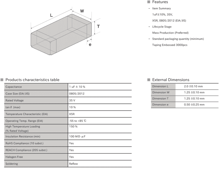
Excellent example of a data summary for a GMK212LD105KG surface-mount capacitor.
At the extreme end, something like a high pin-count FPGA will have a long datasheet reaching hundreds of pages in length. Most of this information is needed to program the device, whereas a PCB layout engineer only needs a few pages of information from these long documents. If the amount of information in a datasheet seems excessive, there is some important information you should focus on as part of component selection and model creation.
Find Important Specifications and Absolute Maximum Ratings
If a datasheet is well-organized the need-to-know specs will be listed on the first page. You’ll usually find a more extensive list of specifications and absolute maximum ratings a few pages into the datasheet. You’ll usually need to use this information alongside data in graphs and charts to calculate more advanced specifications.
Graphs and Charts
Pictures are worth a thousand words, and graphs and charts will nicely summarize a huge amount of technical information in a small space. You’ll likely need to use this data to calculate important specifications not listed in the standard list or in absolute maximum ratings. These graphs are easy to spot as you scan through a datasheet.
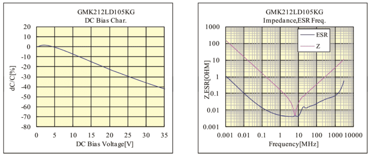
Capacitance vs. DC bias (left) and impedance spectrum (right) showing the self-resonance frequency for a GMK212LD105KG surface-mount capacitor.
Look for Package Information and Pinout
Packaging information, both for 2D and 3D models, will usually appear in its own section of the datasheet alongside assembly information. Oftentimes for ICs, there are different pin layouts or packages for different part numbers, so locating and correctly using the ordering key information is crucial for matching pinout and package information. This information is critical if you’re creating your own component models or if you’re weighing whether to use surface-mount or through-hole components.
“Ctrl+F” is Your Friend
When comparing components, searching for application mentions, or looking for specifications, don’t be afraid to use Ctrl+F to find important keyword mentions in a datasheet. You may need to try multiple keywords to get some useful information, but you can quickly look through a huge datasheet with Ctrl+F.
Your Datasheets, Specifications, and Component Creation
If you need to use information in datasheets for component creation, you’re in luck: I’ve never seen a datasheet that didn’t show package information and/or a CAD drawing of a component. At minimum, a component with a standardized package will have the package type (e.g., LQFP components) listed in the datasheet alongside any other information needed to create the correct component.
For high pin count components, like FPGAs, you’ll spend a lot of time creating component models in your CAD tools. Take a look at the 676-pin FPGA shown below. In total, this component requires 7 schematic symbols to accommodate all pins. Some of these are I/Os, power, ground, differential pairs, and GPIO pins.
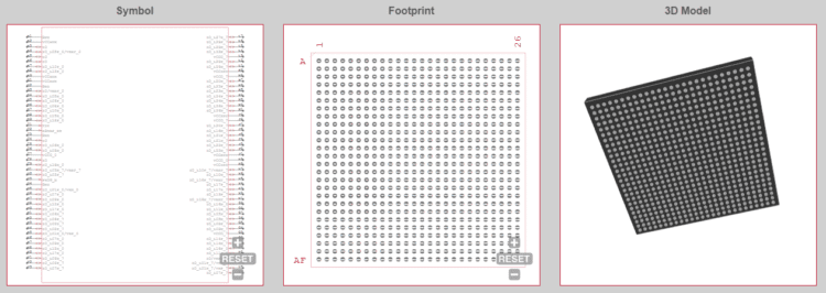
Schematic symbol, footprint, and 3D model for a 676 pin FPGA (Xilinx XC3S4000-4FGG676C)
Putting all this information into schematic symbols takes a lot of time. Some component footprint generators can help you quickly generate the footprint, but these utilities are not available in all CAD platforms. Complicating this is the fact that the datasheet for this FPGA is 217 pages long, which is typical for CPLDs like FPGAs and advanced MCUs.
Instead of scanning through datasheets comparing specifications and looking for component pinouts, you can cut down your search time when you use a parts search engine that provides specification-based searches. This lets you see component specs directly in your search results, and you can quickly narrow down to some candidate components before you start combing through datasheets. You can also take advantage of integrated search features in your CAD applications to quickly fund verified models and datasheets for your components.
Whether you’re creating parts from datasheets or paying for ECAD models from a component creation service, you can find the component data you need from a free parts search service like Ultra Librarian. You’ll have access to a range of 2D and 3D ECAD models from major manufacturers, and you’ll see real-time sourcing information from worldwide distributors. You can then import your ECAD models into popular ECAD applications and use them in your designs.
Footprint and 3D electronic component model creation takes dedicated resources and time, but Ultra Librarian helps streamline these processes. Working with Ultra Librarian will set up your team for success and ensure your finished product matches your design. Register today for free!


")