


When creating new electronics, designers, and engineers must have a common language to describe the components that go into the new project. This language comes in electronic component schematic symbols that unambiguously describe a component’s position, type, and function within a project.
Experienced designers may only need text descriptions of components if they have a reliable memory for electronic component schematic symbols. Schematic symbols can vary slightly depending on the area of the world in which they are found, and designers need to be aware that multiple symbols may mean the same thing. There is a wide variety of electronic component schematic symbols, with this article only covering the most common symbols.
What is an Electronic Component Schematic Symbol?
An electronic component schematic symbol is a pictorial representation of an electronic component, usually standardized by an international electronics industry body. Such standards organizations include:
- International Electrotechnical Commission: IEC 60617 – Graphical Symbols for Diagrams. The IEC database requires a yearly subscription, but designers can access one of the most comprehensive groups of schematic symbols relied upon by engineers worldwide. Most designers and manufacturers use this standard directly or base their own standards on it.
- IEEE/ANSI 315-1975 – IEEE Standard for Graphic Symbols for Electrical and Electronics Diagrams (Including Reference Designation Letters). This common graphical standard for schematics symbols was deprecated in 2019, but many of its symbols are still in common usage, so engineers would be wise to reference it. Designers can access it with a one-time purchase.
- IPC-2612-1: Sectional Requirements for Electronic Diagramming Symbol Generation Methodology. This IPC standard defines strategies for creating new schematic symbols that comply with electronics industry norms. It’s accessible through a one-time purchase.
Historically, CAD librarians needed to memorize many of these symbols or refer to industry reference literature when creating or cataloging components. Today, they are widely available on many reputable websites, along with design footprints and schematics.
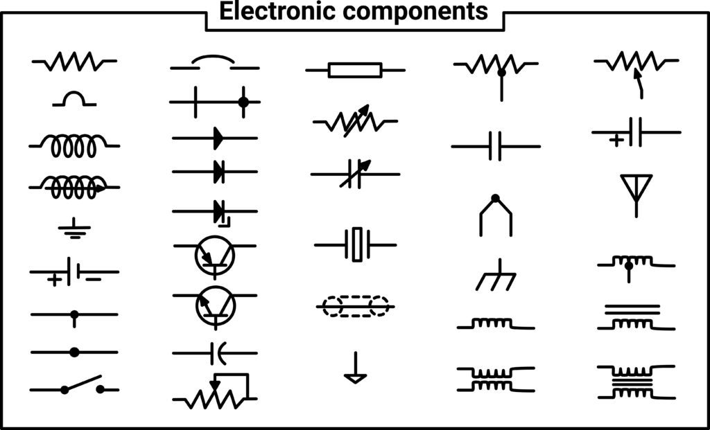
Schematic symbols include a wide variety of component types and circuit features. Most people who have seen simple electrical diagrams are familiar with symbols for resistors, switches, fuses, and other passives. However, electronic component symbols can involve more complex circuit features, such as batteries with single or multiple cells, inductors, capacitors, and transformers.
There are even schematic symbols for some simple machines that may be integrated into a circuit, like buzzers, speakers, relays, and motors. With extremely complex machines, it may be unnecessary, too time-consuming, or too difficult to depict all the components they contain within a schematic. Therefore, schematic symbols can simplify designers’ projects by using a single symbol for complex machines.
Table of Schematic Symbols
It’s important for designers to know many of these older schematic symbols if they are upgrading or analyzing older technology. If a designer or engineer creates completely new electronics projects, knowledge of older symbols is not as essential but may be beneficial occasionally. Given the rapid increase of technology, the new IPC standard governing the creation of new schematic symbols may be especially helpful to designers.
If there are two symbols present for a given component, the first symbol is the international variant, while the second is the United States variant. The symbols shown below follow the IEEE/ANSI specifications, as these are most commonly used in schematic editors in ECAD software. However, many designers and some open-source ECAD programs use the IEC symbols or a mix of the IEEE/ANSI symbols. Due to the popularity of the IEEE/ANSI symbols in major ECAD platforms, they are listed here for reference.
| Electronic Component Schematic Symbols | ||
|
Name |
Symbol |
Details |
|
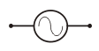
AC Power Supply |
|
|
|
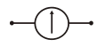
Ammeter |
|
|
|
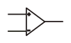
Amplifier (Operational) / Op-Amp |
|
|
|
Amplifier (Voltage) |
|
|
|
Battery |
|
|
|
Battery Cell |
|
|
|
Branching Box |
|
|
|
Capacitor (Non-Polarized) |
|
|
|
Capacitor (Polarized / Electrolytic) |
|
|
|
Capacitor (Variable) |
|
|
|
Cathode Ray Oscilloscope / CRO |
|
|
|
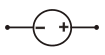
DC Power Supply |
|
|
|
DC Power Supply (Variable) |
|
|
|
Diode (Junction) |
|
|
|
Diode (Light Emitting) / LED |
|
|
|
Diode (Photo) |
|
|
|
Diode (Zener) |
|
|
|
Diode Bridge |
|
|
|
Electrical Appliance |
|
|
|
Filament Bulb |
|
|
|
Fuse |
|
|
|
Galvanometer |
|
|
|
Inductor |
|
|
|
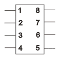
Integrated Circuit / IC |
|
|
|
Loudspeaker |
|
|
|
Microphone |
|
|
|
Motor |
|
|
|
Multiple Conductor Line |
|
|
|
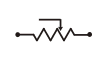
Potentiometer / Voltage Divider |
|
|
|
Resistor |
|
|
|
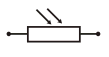
Resistor (Light Dependent) / LDR |
|
|
|
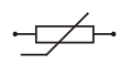
Resistor (Thermal) / Thermistor |
|
|
|
Resistor (Variable) |
|
|
|
Socket Outlet (Telecom Indication) |
|
|
|
Socket Outlet (TV and Radio Aerial) |
|
|
|
Transformer (Iron-Cored) |
|
|
|
Transformer (Iron-Cored, 2 Secondary Windings) |
|
|
|
Transistor (NPN) |
|
|
|
Transistor (N-Type Junction Field Effect) / NJFET |
|
|
|
Transistor (PNP) |
|
|
|
Transistor (P-Type Junction Field Effect) / PJFET |
|
|
|
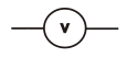
Voltmeter |
|
|


PCB Designers Need Complete Libraries with Schematic Symbols
Today’s ECAD tools generally include most or all of the symbols shown above in their built-in libraries. In addition, most designers don’t refer to one of the standards listed above when adding schematic symbols to a component library. Instead, the most common components are called out with a specific designator prefix (R = resistor, C = capacitor, L = inductor, U = integrated circuit). A schematic symbol will frequently be provided with a note describing the part number or type of component for the designer. As long as the schematic symbol contains the appropriate designator prefix or is a self-explanatory symbol, many designers will not worry about which standard the symbol follows.
The schematic symbol must match the pinout shown in the component datasheets for integrated circuits and connectors and then be added to a component library with PCB footprints and 3D models. Instead of creating every component from scratch, PCB designers can use the best electronic parts search engine to find the component data they need, including sourcing data, specifications, and datasheets for components.
If you’re looking for CAD models for electronic component schematic symbols, Ultra Librarian helps by compiling all your sourcing and CAD information in one place.
Working with Ultra Librarian sets up your team for success to ensure streamlined and error-free design, production, and sourcing. Register today for free.