Electronic symbol for the resistor

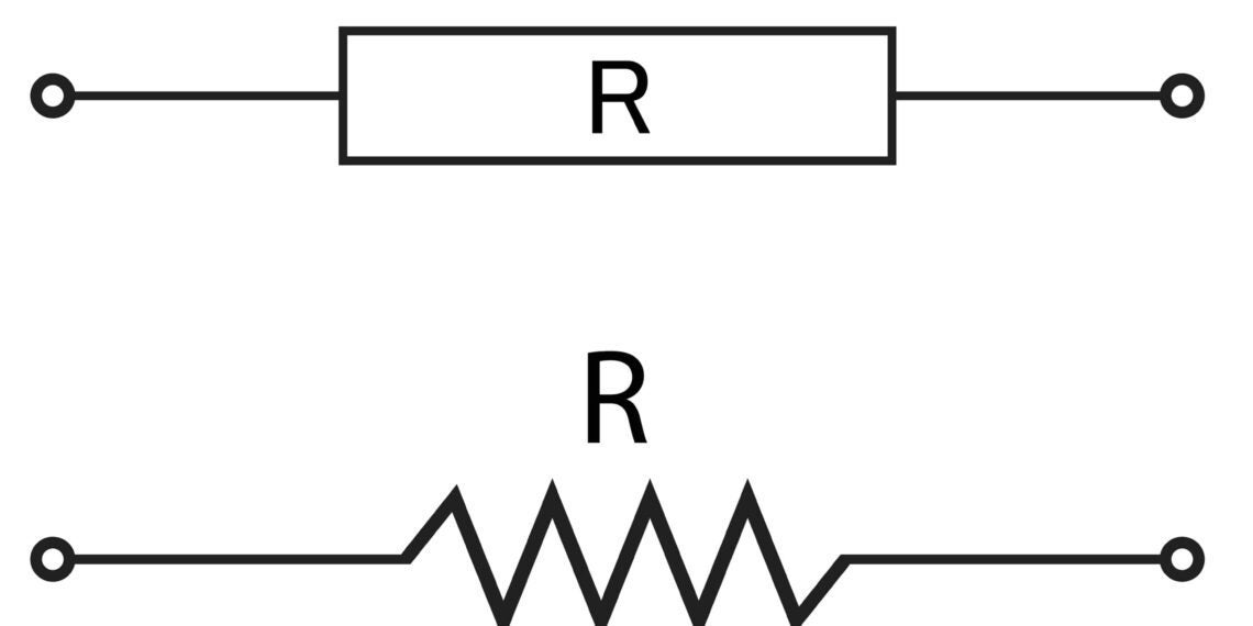
A basic electronic symbol

When designers don’t understand what components are being used and how they are interconnected, the PCBA development process can come crashing down around them. Therefore, a solid understanding of basic electronic symbols and their functions is critical for designers and engineers whose work dictates the success of the rest of the PCBA development process. Let’s take a look at some common symbols that should be well-known and understood.

Commonly Used Basic Electronic Symbols and Their Functions

When you hear the language used to describe the building of electronic circuits, boards, and systems, the reference is invariably to a software language—Basic, FORTRAN, C/C++/C#, Java, Ruby, HTML, XML, etc. Yet, there is also an electronics hardware language, and it is utilized by professionals in all industries where electronic systems are a part of the system design. This language is electronic symbols.

Knowing electronic symbols and their functions within circuits or systems is critical to understanding operation and expected performance. In fact, the crucial stages of design and testing are not possible without this important knowledge. Thus, it may be useful to take a look at some of the basic types of electronic symbols, as shown in the table below, and review the function of the components and/or elements of which they are comprised.

Table of basic electronic symbols

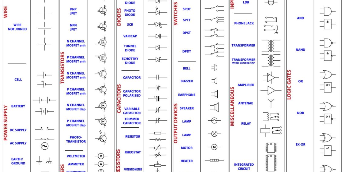
Common electronic symbols

Wires

The most basic electronic symbol is the wire, which represents a physical electrical connection between two or more points. Minimally, a wire should have a source connection and termination point. In order for current to flow between connected electrical points, or nodes, the wire must be continuous or unbroken.

Power Supplies

Another fundamental element for an electrical circuit to operate is a power supply. In many cases, power supplies may not be located on the circuit board to which they furnish power. However, when the power supply is a component, it will likely be one of those shown in the figure, such as a battery. It is noteworthy to understand why ground symbols are included here. As an electrical circuit must be a complete path from the source and back to the source, current must flow into and/or out of ground.

Transistors

The transistor is also a common active component, as it is used for switching and amplification in many applications. Although there are many types of transistors, the BJT, JFET, and MOSFET are the most common ones.

Meters

Being able to test and verify that an electronic circuit performs as intended is essential. Meters are used to indicate what type of testing equipment to employ and where to connect them. Ammeters and voltmeters are the most common meters found on circuit diagrams.

Diodes

Diodes are single junction—P material and N material—devices that are primarily used for switching and isolation. There are several specialized types of diodes and it is good to know at least some of these. For example, Zener, Schottky, and LED diodes, which in addition to being used as indicators on PCBAs, are some of the most common lighting components today.

Capacitors

Capacitors are one of the most basic energy storage devices. Capacitance itself is always present in electrical systems, whether wanted or not. A useful property of capacitors is they block DC and pass AC, which makes them excellent signal couplers for RF applications.

Resistors

The resistor is the most basic passive component. This component exemplifies Ohm’s Law. That is, that the resistance of the device is equal to the voltage across divided by the current flowing through it.  Not only is the resistor the most basic electronic component, but it is probably the most used as well.

Switches

Switches are essential for electronic circuit operation, as they control when a system or subsystem is active or inactive. Switches may connect single sources with many outputs, for example, SPDT, or vice versa.

Output Devices

The various types of output devices that may be found on circuit boards or in electronic systems are quite large, and many are specialized or custom. However, some common types to be familiar with are buzzers, antennas, speakers, lamps, and motors.

Input Devices

Input devices to electronic circuits are typically electrical signals. A common source is a microphone.

Miscellaneous Devices

This category includes a number of common components and devices such as transformers, op amps, and chips, which necessitate organization or an IC library due to their similarity of footprints.

Logic Gates

Logic gates, such as AND, NAND, and XOR, are basic components of digital electronic circuit design. However, these components also are embedded in other components such as processors and FPGA ICs.

How to Best Source Basic Electronic Symbols

Having a clear understanding of basic electronic symbols and their functions will aid you in designing and developing electronic boards and systems. Armed with this knowledge, you can better source components and devices for your projects. However, if efficiency and accuracy are on your list of requirements, then you should probably opt for the largest online parts library that provides free footprints and symbols for your design, such as the TIP3055 and TIP2955 BJT equivalents shown below.

Commonly used BJT transistor pair

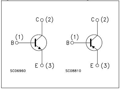
The TIP3055 and TIP2955 NPN and PNP BJT Equivalents

If you’re looking for data and information on basic electronic symbols and their functions, Ultra Librarian helps by compiling all your sourcing and CAD information in one place.

Working with Ultra Librarian sets up your team for success to ensure streamlined and error-free design, production, and sourcing. Register today for free.

UL-Icon.png

The Ultra Librarian Team

Ultra Librarian offers the world’s largest PCB CAD library, putting cutting-edge materials at your fingertips so you can build better products faster—all for free.

Join Our Newsletter

Subscribe to our newsletter to receive the latest news, and important updates

Name(Required)

Related Posts

If you’re looking for any of our component footprints or models, we have readily available and free options for you and your design team. Search our library for the solution you’ve been looking for.

Free Design Resources

Ultra Librarian is the worlds largest online – and always free – PCB CAD library. Build products better, faster, and more accurately with easy access to vendor-verified symbols, footprints, and 3D models. Register today to start searching the right components for your next design.

Recommended