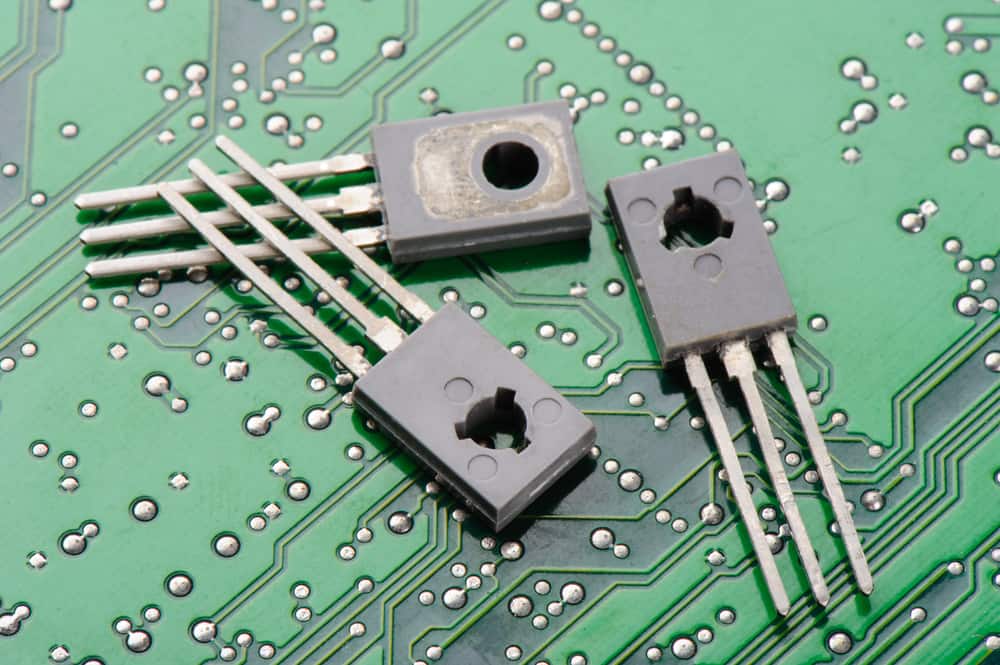
NPN and PNP Power Transistors
It is remarkable how much genealogy is reflected in the software and hardware systems that we use daily. For example, there are software programs based on evolutionary learning where an initial assumption of genes or variables are continually updated—through selection, mutation, and recombination—to arrive at a superior result. Then, there are electronic components that seem to mirror some characteristics of twins. The most common correlation is between mirror-image twins and complementary components.
Mirror-image twins are identical twins; however, their embryos separate later than the normal first week. Interestingly, this slight change can have a significant impact. For example, the developmental patterns for these twins can be exactly opposite to each other. For complementary parts, such as the TIP2955 and TIP3055 equivalents from STMicroelectronics, this is exhibited in their inverse operation. Let’s take a more detailed look at these complementary components and their interesting relationship.
TIP3055 and TIP2955 Applications
One of the most important utilizations of active components in any signal processing system is amplification. In some applications, such as communication systems, there may be several amplification stages. In order to satisfy a wide range of amplification requirements, there are several common types of amplifiers, as listed below.
Common Amplifier Types
- Class A – single transistor, conduction angle: 𝛿 = 360°
- Class AB – push-pull design, with each transistor conduction angle: 180° < 𝛿 < 360°
- Class B – push-pull design, 𝛿 = 180°
- Class C – single transistor, 𝛿 < 180°
- Class D – utilize PWM
The amplifiers listed above are often implemented using BJTs, and although BJTs may be used for other amplifier types—Classes E, F, and G—it is not common to do so. Instead, FETs (JFETs or MOSFETs) are utilized most often. The TIP2955 and TIP3055 equivalents are, however, readily used for the push-pull designs listed above, with the analog input signal applied to each for a half cycle. Specifically, these amplifiers are used for high power applications due to their electrical characteristics.
Attributes of the TIP2955 and TIP3055 Equivalents
The primary attribute that makes the TIP3055 and TIP2955 such good options for Class AB and B amplifiers is their complementary design, illustrated in schematic form below (from the TIP3055/TIP2955 datasheet).

TIP3055 and TIP2955 Schematics
By connecting the emitters of the equivalents and adding the passive components, you can create a push-pull design such as the one shown in the image below.
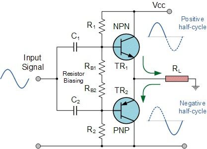
Push-pull amplifier example (image from Electronics Tutorials)
When implementing the TIP2955 and TIP3055 equivalents, high power amplification is possible due to the maximum capabilities of the transistors. These include up to 100V and 15A collector voltage and current, respectively, along with the other parameters listed below.
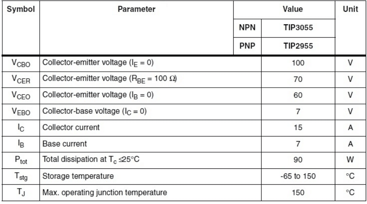
Maximum ratings for the TIP2955 and TIP3055 equivalents.
To utilize these amplifiers most effectively, you should take advantage of the data available from the datasheet as well as models that are best sourced from online resources.
Designing With the TIP2955 and TIP3055 Equivalents
Designing with equivalents can be as easy as designing with single devices, provided you remember that all electrical parameters—such as those shown in the table below for the TIP3055 NPN—are negative for the TIP2955 PNP.
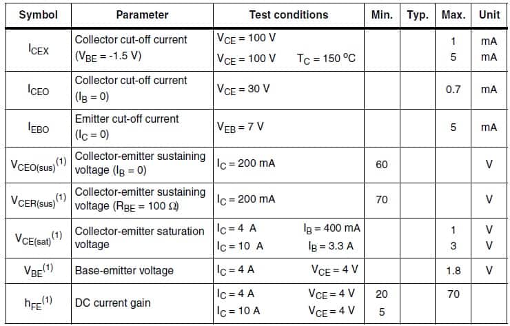
TIP3055 Electrical Characteristics
However, for design optimization when using transistors, it is often required that regions of operations are well-defined. For BJTs, this translates into finding the device characteristic or I-V curve. The best means for determining this critical parameter is to employ a digital circuit simulator that will allow for testing a range of scenarios.
Once you have your circuit optimized, you then need to create the PCB layout and associated design data files for your board build. For manufacturability, this data must conform to the design for manufacturing (DFM) rules and guidelines of your CM and be in a format that facilitates accurate transfer. For DFM guidance, you should rely on your chosen manufacturer(s) and for design accuracy, you should look for a supplier of free CAD model data, including accurate footprints.
If you’re looking for CAD models for common components—including complementary parts such as the TIP2955 and TIP3055 equivalents—Ultra Librarian helps by compiling all your sourcing and CAD information in one place.
Working with Ultra Librarian sets up your team for success to ensure any design is going through production and validation with accurate models and footprints to work from. Register today for free.