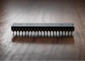
In order to avoid the potential output glitches, power dissipation, and current flow problems of the SGS L293, the SN754410 was designed as a replacement. The SN754410 is an electronic component optimized for drivers such as stepper drivers, latch relay drivers, and DC motor drivers. It transmits control signals to motors and actuators. There are many variants of this component available from different manufacturers, but its standard characteristics are captured in publicly accessible datasheets.
The SN754410 Datasheet
The SN754410 is described as a high-current driver component, able to handle bidirectional current. It is designed for DC current and must be powered by at least 4.5 V to function properly. Its maximum voltage tolerance is 36V, and its maximum amperage tolerance is 1 A per output channel. Current flow is stable in a wide range of temperatures, from -40 degrees Celsius to 85 degrees Celsius.
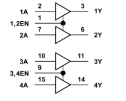
Current can flow in different directions on either side of the component, but is not required to do so. If only one side of the component is in use, its configuration is called a half-bridge. When both sides of the component are in use, the configuration is called a full bridge. Each side of the component has its own input power, output channels, ground, and heat sink.
When both sides of the component are active, each side must be connected to its own power source. In this case, one side of the component is dedicated to input power and logic, while the other side of the component handles output. Both inputs on a given side of the component must process high voltage current in order to create high voltage output. If one input isn’t receiving enough current, the output current will drop even if the second input is receiving enough current to power both inputs. The datasheet explicitly states power supplies to the inputs may differ in voltage as long as they both provide at least 4.5 V to their respective inputs.
Considerations When Using the SN754410
Many high current components have requirements for powering up or powering down. These involve specific steps executed in sequence to prevent current flow problems, overheating, or other hardware issues. The SN754410, according to its datasheet, does not require any extra steps. However, this does not necessarily mean all projects containing this component can be shut down with a simple switch. Other components compatible with the SN754410 may have these requirements. Designers should not assume simple shutdowns are always possible with the SN754410.
The datasheet explicitly mentions how the SN754410 is vulnerable to damage from electrostatic discharge. Therefore, designers should be aware that reducing static is vital to the successful handling of this component. This may involve packing in conductive foam, reducing static in the workspace, or other preventative measures.
It is good practice to ensure all parts of the SN754410 are grounded before using them, and it is important not to touch the leads unless absolutely necessary. Static electricity can induce current inside the component it is not designed to handle, making it more likely to suffer spontaneous failure. Most integrated circuits and electronic components are vulnerable to static like this, but it is important to remember high current components are not immune.
Finally, it is important to remember inputs and outputs should be used in pairs on the SN754410. This is because outputs are in phase with their inputs. The component is designed for a half-bridge or full-bridge configuration, not a “quarter bridge” or “three-quarter bridge.” Failing to use inputs and outputs in pairs could damage the component and any other component connected to it.
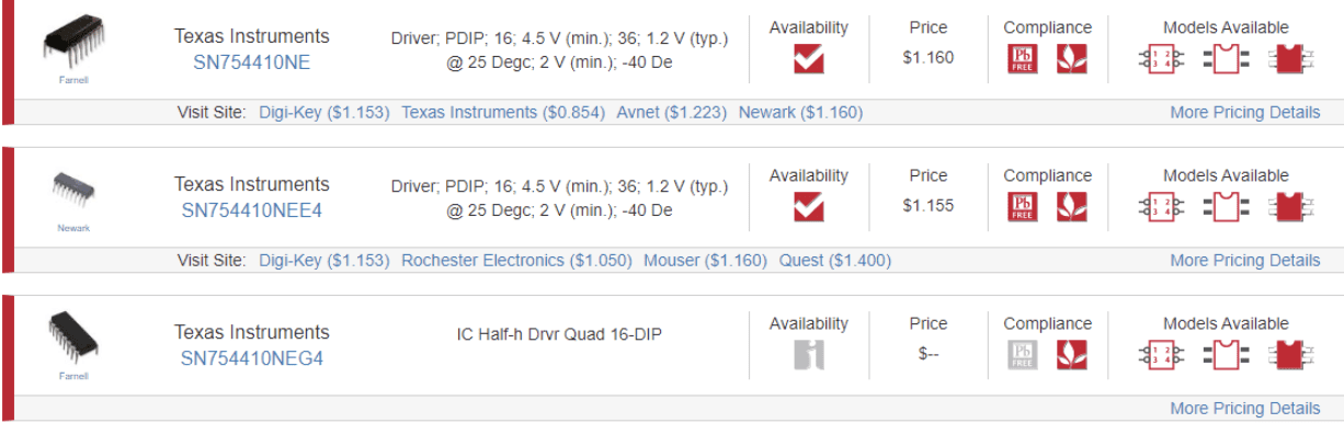
SN754410 Versions
Different versions of the SN754410 may have slightly different technical specifications. Some specialized versions of the component have a slightly higher voltage tolerance, while others may be able to handle a higher amperage in one or all of their output channels.
Since all variants have the same number of inputs, outputs, circuits, and pins, there aren’t any major structural variations likely to influence a designer to pick one variant over another. An interesting reason for picking one variant over another, however, could be its schematic symbol. Some versions of the SN754410 are associated with extremely simple schematic symbols, while other symbols are far more complex. If a designer is creating an electronics project with many components—particularly if the SN754410 is configured in a full-bridge—a variant with a more detailed symbol may be better during the design phase.
Ultra Librarian provides multiple SN754410 variants for designers—enabling them to choose the most precise component for their project. Working with Ultra Librarian takes the guesswork out of preparing for your next great device and puts your ideas on the road to success. Register today for free!


")