
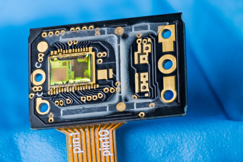
Following good rigid-flex PCB design guidelines are important for medical device designs like optoelectronic sensors
When military and aerospace requirements resulted in the creation of flex circuitry seventy years ago, who knew that they would become such an integral part of electronic design today. Yet they are now found in everything from simple greeting cards to life-saving medical device designs. And as with their older siblings, the standard printed circuit board, flex, and rigid-flex circuits are built according to a set of three IPC performance classifications depending on their intended use:
Let’s take a closer look at these rigid-flex PCB design guidelines and see how they are applied to flex circuitry.
Breaking Down the Three Classifications for Building Electronics
In the chart above, you can see the three classifications IPC defines for building electronics and the applications those classifications are intended for. Applications that are considered mission-critical, such as aerospace or medical devices, need an assurance of performance reliability, requiring greater precision in design, manufacturing, and testing. Other applications that are not as critical can opt for less precision in manufacturing, saving time and money.
Precision in electronics manufacturing requires different design requirements and more rigorous fabrication steps, all of which add up to higher manufacturing costs. Although PCB design is precise, holding tighter tolerances requires more effort during manufacturing. Take annular ring breakout, for example, a condition that happens if the drilled hole doesn’t quite match up to its intended metal pad. The lack of an annular ring all the way around the hole can lead to soldering problems and long-term reliability concerns. For throw-away electronics, like the flex circuit in a singing greeting card, this is not a concern as a certain amount of scrap is expected. But for an embedded pacemaker, the potential for failure could be disastrous, and the same level of defects are not allowed.
Breakout doesn’t necessarily mean failure of the flex circuit, and class one electronics will allow a certain percentage of these conditions to go through. In addition to breakouts, class one electronics will allow thinner platting along with less rigorous manufacturing and testing processes. In some cases, fabricators will use class two requirements in their processes so they can assure their customers of higher levels of quality in their work. The key is to match your project’s requirements to the correct class of rigid-flex PCB design guidelines for ultimate success.
Examples of Rigid-Flex PCB Design Guidelines for Class Three Electronics
There are many rules and guidelines for rigid-flex circuit layout, and these details can be found in the IPC-2223 and IPC-6013 publications. Here are some design violations to avoid during the layout of rigid-flex circuits:
- Vias placed in the bend of the flex circuit
- Drill to copper clearances in flex materials
- The amount of flexibility of the circuit vs. the design’s layer count
- Using sharp angles in trace routing through flex areas
All of these errors can lead to the premature failure of the flex circuitry or a direct short during manufacturing. However, it is important to remember that the specifics of these design rules can change depending on what class of rigid-flex circuit you are designing. For example:
- Class three designs are not allowed to have any copper voids in the barrel of the plated hole.
- Class two designs are permitted to have one void in a hole as long as there are no more than 5% of the total number of holes with this flaw.
Another example is with annular rings. In class one and two designs, some breakout is allowed where the drill hole is not completely contained within the annular ring of the pad. But in class three designs, breakout isn’t permitted at all. To prevent this, designers will want to change their design rules for increased pad sizes and object clearances.
Surface finishes are also handled differently depending on the class of the rigid-flex design. In all classes, any surface finish voids cannot exceed 90 degrees of the circumference of the hole. However, the number of voids changes with each class:
Now that we’ve looked at some of the design guidelines for rigid-flex circuits let’s talk about what class your next design will need.
Do You Need Class Three Requirements on Your Rigid-Flex Design?
To make the right class choice for your rigid-flex design, start first by contrasting cost with reliability. Class three designs will need higher quality materials to meet reliability requirements, while the lower classes can use materials that are more standard and cost less. Class three designs will also require tighter controls and precision in manufacturing, adding up to greater costs, while classes one and two won’t. You will also need to consider testing and inspection, which will also be more involved for a class three design and at a higher cost. However, the key to making your determination is to balance the cost with the application the rigid-flex is intended for. Is it mission-critical? If so, then class three will be your first option.
As a designer, you’ve got a lot of choices to consider for your next rigid-flex design. Here is where partnering with Ultra Librarian can help you save time and money by making the right component choices and providing you with technically accurate CAD models. The Ultra Librarian platform delivers PCB footprints, models, and technical data that is verified by component manufacturers and available on popular ECAD applications.
If you’re looking for CAD models for common components or helpful information like rigid-flex PCB design guidelines to improve your development process, Ultra Librarian helps by compiling all your sourcing and CAD information in one place.
Working with Ultra Librarian sets up your team for success to ensure streamlined and error-free design, production, and sourcing. Register today for free.


")
")