
Applying 3D CAD modeling best practices
Knowing and following best practices can be considered a standard operating procedure or SOP for creating good PCBA designs. For example, failing to follow the best PCB layout guidelines may render your design unmanufacturable, at least without timely and costly redesign(s). Likewise, the same diligence is required for successful ECAD/MCAD integration.
Whether the process is from ECAD to MCAD or MCAD to ECAD, integration requires a file format accessible by the programs that perform each design. The 3D STEP file is the most commonly used CAD format for this purpose. However, maximizing the efficiency and quality of your integrated PCBA development process requires understanding and applying 3D CAD modeling best practices.
Understanding 3D CAD Modeling Standards
Regulations and standards govern the PCB development process. This applies to the design, manufacturing, fabrication, assembly, and testing stages, as illustrated in the figure below.
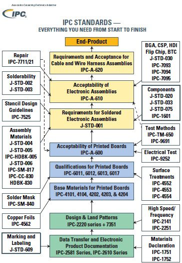
IPC Standards for PCBA development
The standards listed above are not exhaustive. However, it does accurately convey the importance placed on oversight to ensure that electronic circuit boards are built to meet specified performance criteria and safety requirements. These requirements apply to all PCBAs. There is yet to be an industry-wide standard that all 3D CAD models must adhere to.
3D CAD modeling formats have been created; however, they are generally accepted as standards. These models can be divided into native and neutral, some of which are listed below.
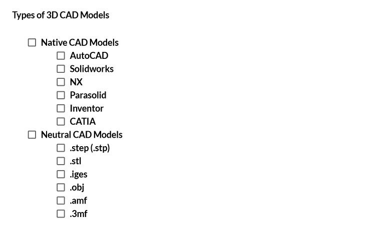
Native and neutral CAD model formats have advantages and disadvantages. The most significant advantage of a native 3D model is that it is designed to work well with the program that creates it – often exclusively – therefore, it is likely to be more detailed and specific than a neutral CAD model. On the other hand, neutral models provide flexibility and allow you to work with various design packages and CMs for your board build. Irrespective of the model you select, it is essential that you employ good CAD file management guidelines.
CAD File Management Guidelines
One of the most under-discussed issues when developing PCBAs and electronics-based products are the need for good data management. Some advanced PCB design packages inherently include product data management (PDM) or product lifecycle management (PLM) capability. Your CAD file management solution should consist of component library management to be the most effective. However, additional best practices should be considered for 3D CAD modeling, as listed below.
Failing to include the straightforward guidelines above can wreak havoc with your product development, often resulting in data loss, unnecessary redesigns, and missed deadlines. Including these rules, however, goes a long way toward establishing an optimized PCB development process for your 3D CAD model design.
3D CAD Modeling Best Practices for PCB Fillets
3D CAD models of electronic components and PCBAs are most often needed for ECAD/MCAD integration. For example, when case or enclosure specifications influence the design of the PCBA. Issues may include the placement and orientation of components that must be accessible or visible at the surface of the enclosure. Board size, shape and location of cutouts may also be major concerns that must adhere to mechanical dimension constraints.
It is common for changes, such as adding a fillet, to be necessary to satisfy design restrictions or remove a sharp edge that may pose a problem. The best practice is to employ automation software when adding fillets, as any structural changes will permeate throughout the board stackup. And ensuring that your updated design passes all DRC checks and is manufacturable can add significant time to the design process. However, some best practices should be followed if this capability is not included in your design program.
3D CAD Modeling Best Practices for Fillets
- Use fillets as safety features
- Use fillets to improve handling
- Use a fillet when a vertical wall meets an angled surface
- Use a fillet when two vertical walls meet at less than 180°
- Ensure all users are skilled in making drafting modifications, such as adding fillets
- Do not use fillets for 3D printer designs
- Avoid using bottom-edge fillets
The use of 3D CAD models by PCBA designers is increasing. Therefore, it is important to know best practices and have access to tools; such as an easy-to-use, readily accessible, and comprehensive CAD file reader, to aid you in ensuring your 3D CAD file model design integrates with MCAD requirements and is manufacturable.
If you’re looking for CAD models for common components and important guidelines such as 3D CAD modeling best practices to help you optimize your board development process, Ultra Librarian helps by compiling all your sourcing and CAD information in one place. Working with Ultra Librarian sets up your team for success to ensure streamlined and error-free design, production, and sourcing. Register today for free.


")