
Mechanical design to electrical layout and automation, it’s imperative to consider all the potential elements you will come across.
Although they were created in 1928, Reese’s Peanut Butter Cups rose to a higher level of popularity in the 1970s with the introduction of a new series of commercials. After bumping into each other, two people would realize that the accidental blending of their chocolate and peanut butter treats was actually “two great tastes that taste great together.” Yet while this principle of the whole being greater than the sum of its parts has been a recognized truth for ages, it took a long time before it was put into practice in mechanical and electrical design.
For years the design process was broken up into two different parts, mechanical and electrical, and separate design systems and processes were used for each. Thankfully the mechanical design to electrical layout and automation process has finally been blended together. Modern CAD tools will work together now to join both the MCAD and ECAD processes to bring about new levels of efficiency and quality to manufacturing. This article will look at these processes, and how by understanding them, you can leverage these capabilities in your own design process.
Mechanical Design to Electrical Layout and Automation, the Differences Between the Tools
First, let’s review the differences between mechanical and electrical CAD systems:
- Mechanical design tools, or MCAD, allow engineers to create physical objects and parts. Variations of these tools are used for everything from toy building blocks to massive multi-level buildings. Designers can work within 2D or 3D environments, run different simulations on the structures, and output the information in standard manufacturing documentation such as files or CNC machine code.
- Electrical design tools, or ECAD, allow engineers to connect different electrical signals, or nets together within a schematic, integrated circuit design, or printed circuit board layout. In the case of circuit board design, the nets in the schematic drive the physical design of the board in the layout tools. This work is done in a 2D environment using different colors to represent the various layers of the board, and the systems provide automated rule checking and circuit simulation. Once completed, manufacturing data is generated in industry-standard formats.
Both systems offer a different approach to design according to the needs of their users. MCAD systems focus more on the physical representation of their structures so designers can see exactly what they are creating in 3D and how their designs interact with other objects. ECAD systems on the other hand focus on the electrical connectivity of potentially thousands of different nets that have to be monitored for both electrical and physical rule adherence.
Each of these systems has traditionally been constrained by the amount of computer resources available to them. Some older ECAD systems for example were unable to fully render negative plane images and marked a connection with a simple “X.” However, as larger computers with greater system resources became available, CAD systems began to increase their capabilities. Today’s MCAD and ECAD systems have the ability to exchange data with each other to provide visual and automated rules checking. Next, we’ll look at how these blended CAD capabilities can work together.
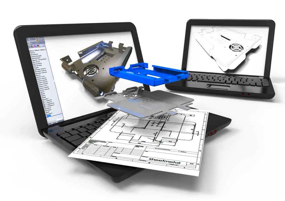
Mechanical design of an electronics enclosure
Mechanical and Electrical CAD Systems Working Together
One of the first benefits of blending MCAD and ECAD was transferring physical board data from the mechanical design team to the PCB layout team. Since the mechanical engineers were already specifying the size and shape of the circuit board along with its mounting hole and supporting hardware locations, it simplified the design cycle to transfer this data into the ECAD system. Then, in the same way, the ECAD design data would be transferred back to the MCAD systems. This allowed the mechanical designers to verify component placement locations to system enclosure features and verify the form and fit of the entire system.
But there is much more that can be done with MCAD and ECAD systems than simply verifying the fit of circuit boards in a chassis. As designs get faster and more complex, advanced simulation and modeling will be needed for not just the electronics, but the physical design as well. One example is the need for thermal modeling to design the dissipation of heat within a system enclosure. Computational fluid dynamic analysis will be needed to determine the most optimum airflow throughout the system to provide the necessary cooling for high-speed electronics.
To accomplish these different tasks, both MCAD and ECAD systems are constantly improving their capabilities to interface with each other. New transfer protocols and data structures are being formed to allow seamless communication between systems. Additionally, the systems themselves are growing in their capabilities. Most major PCB layout tools now offer 3D capabilities to verify clearances to other mechanical objects such as imported enclosure data from MCAD systems. The next question then is how does all of this blending of CAD systems and automation benefit printed circuit board manufacturing, which we will look at next.
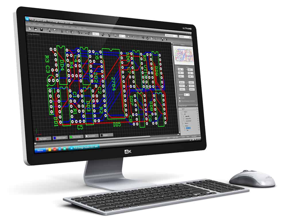
The layout of a printed circuit board
The Benefits of a Blended Tool Environment for Efficient Manufacturing
The enhancements of both MCAD and ECAD systems, and their ability to work together in the design of printed circuit boards, open up a vast range of virtual prototyping capabilities during PCB layout.
Many errors that in the past weren’t discovered until physical prototypes were built are now being discovered virtually before the board is sent to manufacturing. These errors include the physical fit of the PCB within the system enclosure and the location of interfacing parts such as connectors and plugs for accessibility.
It used to be commonplace to find problems such as a reversed connector pin-out in the physical prototype that would send the design back to the drawing board. Now, connector pin-out data can be modeled when virtually prototyping the circuit board and corrected before time and money are committed to manufacturing.
Another advantage to virtual prototyping is to determine the form, fit, and function of the parts being used on the board. Engineers can see which parts will work in their design before committing to component purchases using bill of materials software that determines price and availability. Tools like this further reduce the chance of stalled production and ensure that you are getting the right parts for your design.
Working with Ultra Librarian is also another essential part of successfully designing your circuit board. The Ultra Librarian platform gives you access to PCB footprints and technical data developed with IPC standards in mind. Ultra Librarian’s footprint data is also compatible with popular ECAD applications and verified by the component manufacturers helping you to develop the highest quality in your design.


")