

Newer engineers, startups, students, and non-EE stakeholders in a project often look for online tools or free programs to help them get started with new designs. The first step in any project is to work through front-end engineering tasks involving components selection and system architecture. Online schematic drawing tools should simplify these front-end tasks and help a design team get to the electrical design stage quickly.
If you’ve never used an online design tool to build electrical diagrams or schematics, these tools can become part of your front-end engineering and design workflow. The best online schematic editors and drawing tools will give you access to real component data rather than forcing you to browse distributor websites. Some important aspects of design and engineering can be streamlined with this type of direct connection to the supply chain. Keep reading to learn more.
Getting Started With a Schematic Diagram Tool Online
One of the newest online schematic diagram tools is Digi-Key Scheme-It. This online platform gives users an easy way to find and place components in a block diagram, circuit diagram, or electrical drawing. Digi-Key Scheme-It is one of many tools that helps users quickly create a schematic diagram that can then be used inside a standard CAD package. The tool’s main strength is direct access to Digi-Key’s extensive parts catalog, which aids sourcing and helps ensure you won’t be surprised by a component shortage.
Here is one type of workflow where you can implement Digi-Key Scheme-It into your design process.
Block Diagram Creation
When creating a system-level architecture for a new product, a block diagram is the best way to get started. One standard practice is to do this in the same program you would use to create the electrical schematics for a PCB layout. Starting here helps you stay organized once you’re ready to create the schematics for your system.
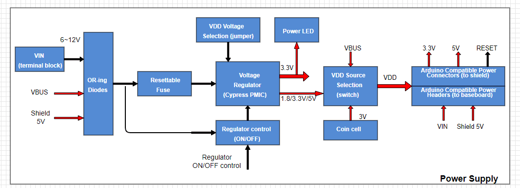
Example power supply block diagram in Digi-Key Scheme-It.
Upload BOM
If you’ve already scoped out the major components you’ll need for your design and created a preliminary BOM; you can upload this to the platform to get started with component selection. As long as the data is in Excel format and MPN/supplier part numbers are available, the schematic editor can pull data for any available components from Digi-Key’s catalog. Users can then drag these symbols and other components into the schematic to start creating a new design.
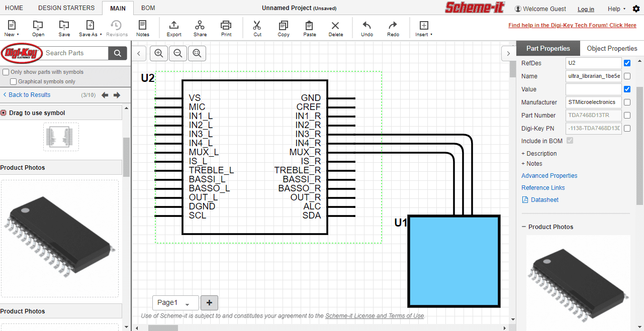
Symbol Creation
Some components don’t have available schematic symbols, or proprietary components are being used that require custom symbols. In this case, you can assign a generic symbol to a component or create a symbol from some easy-to-use drawing tools. If you want to use an alternative component whenever a part does not have a symbol, one of the useful search features in Digi-Key is its search filter. The search feature pulls components from Digi-Key’s catalog, and there is an option to only show components with existing symbols.
Export Your Design
Once you’ve finished your initial schematics and block diagram, it’s time to import it into a CAD program. Today’s CAD programs have translators that can convert between schematic and PCB layout formats. The Digi-Key Scheme-it platform can export your design into the native KiCAD format with .sch and .lib files. These file formats can then be imported into major platforms like Altium, Cadence, and Siemens (formerly Mentor). Once imported into these CAD programs, the user can finish the design in their preferred CAD file format.
Starting with an online platform like Digi-Key gives designers a way to streamline some of the front-end design tasks involved in creating a new design. Schematic creation is also an exercise in sourcing. Selecting parts based on inventories from one of the world’s largest distributors gives designers confidence that they won’t get blindsided by a shortage. Accessing symbols and footprints for the design instantly also cuts down the amount of design work; these data will be included in the design export and can be modified once in a standard CAD program.
Designs created as a mixed schematic + block diagram format can be exported in KiCAD format and translated into other CAD formats.
Another option is to export the design directly as an image (PNG/SVG formats) or as a PDF. These can then be shared as part of a design review before finalizing the design and importing it into a CAD program. Once you’ve finalized the design and converted it to your native CAD format, you’re ready to perform any cleanup and fill in any missing functional blocks in the schematic.
Other Ways to Speed Up Front-End Engineering
Several other tasks can be performed as part of front-end engineering in Digi-Key Scheme-It. The platform includes several different tools that let you create some standard drawings and documentation:
- Schematic cover pages
- Block diagrams, both circuit-level and system-level
- Logic diagrams and circuit diagrams that are not component-specific
- Flowcharts for algorithms or workflows implemented in the end product
- A bill of materials compiled from Digi-Key’s catalog data for your components
Each schematic can then be downloaded as its own page and added to a new PCB design project as a standard schematic. You can then use your CAD tool’s built-in outputs generator to create shareable PDFs for your team members. You can also add on to these schematics with components from other distributors.
If you’re looking for components you can add to your system and source these through other distributors, use the parts search features in Ultra Librarian. The Ultra Librarian platform gives you access to PCB footprints, technical data, and ECAD/MCAD models alongside sourcing information to help you stay ahead of supply chain volatility. All ECAD data you’ll find on Ultra Librarian is compatible with popular ECAD applications and is verified by component manufacturers to help streamline your designing process.
Working with Ultra Librarian sets up your team for success to ensure streamlined and error-free design, production, and sourcing. Register today for free.


")


