 Electronic components are often evaluated as if they will operate in a vacuum. This helps isolate the effects of varying a single attribute without consideration of external influences. However, actual usage will be affected by the electrical characteristics of input and output signals.
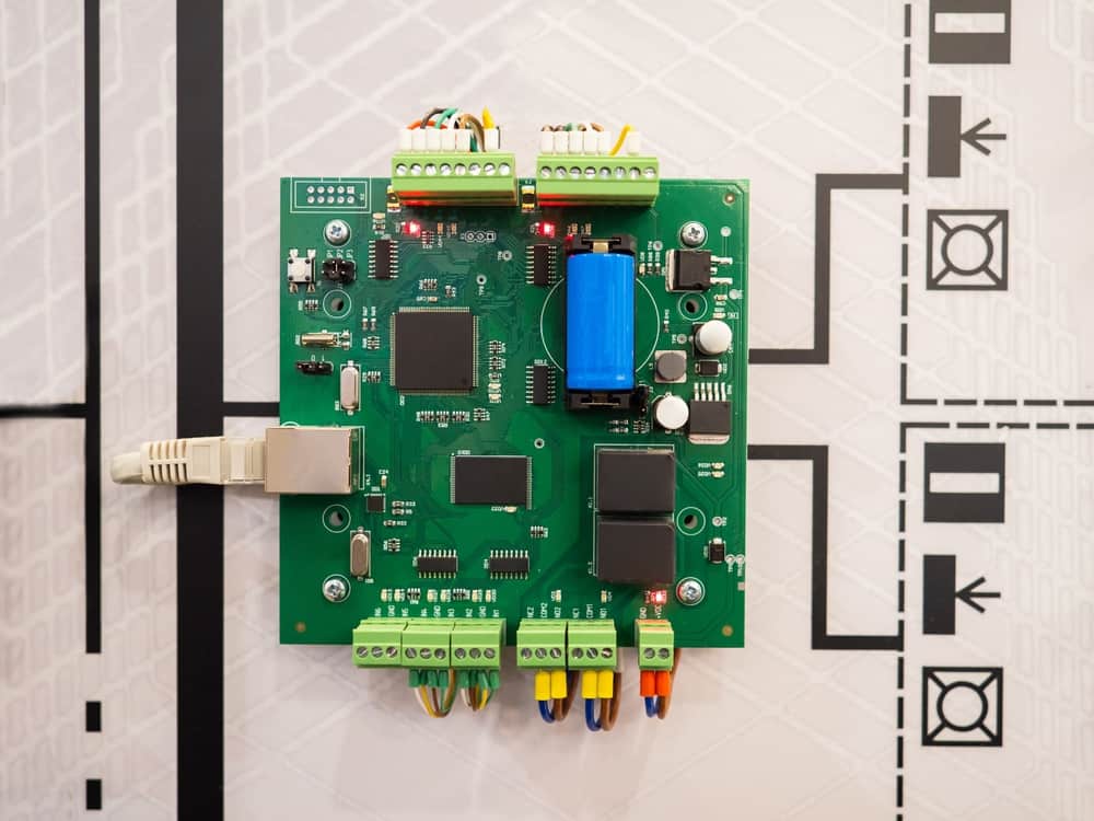
Accepting input signals, processing them, and supplying the proper outputs is the primary function of virtually all PCBAs. And the board’s effectiveness at performing this task is determined significantly by the parts used to connect with external devices, boards, and systems. Therefore, choosing the right power and signal connectors and following best practices for their incorporation into your design is essential.
Power Connectors: Usage and Types
There is a trend in the electronics industry to integrate power and signal transfer over a single cable, such as USB-C. Yet, many cases use dedicated power and signal connectors as a better interconnect option. For example, industrial applications that require rugged cables, continuous connection, and voltage and current levels may present more outstanding EMI/EMC issues.
Power connectors typically perform one of the following functions:
- Accept AC from an external source. For example, a wall outlet or power supply.
- Accept DC from an external source. Most often from a linear or switch-mode power supply.
- Connect to a portable co-planar supply, such as a Li-Ion cell or battery pack.
- Deliver or distribute power to a load device, interconnected PCBA, or external system. This typically requires power management and control, which includes voltage or current regulation.
Power connectors come in a multitude of shapes and sizes. However, the need for ease of use for consumers has led to the IEC 60320 standard. This international standard regulates connectors for appliances up to 250V, with specification emphasis on safety.
Signal Connectors: Usage and Types
Safety is also important for signal transfer; however, maintaining signal integrity, especially for low amplitude signals, is the primary concern. This is true for wired and wireless transfers. Signals can be classified as one of three types, as listed below.
Basic Types of Signals
- RF signals
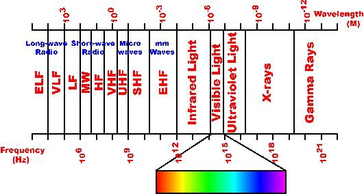
Classes of RF signals. Image from
As shown above, RF signals span the entire electromagnetic spectrum and are separated into classes based on their frequency range. These ranges also define electronic connectors, cables, and other components.
- Digital signals
Today, USB connectors are heavily utilized for digital transfer over cables. However, many connectors also facilitate wireless communications, including IoT connector modules. - DC signals (often power signals)
Many signal connectors are standardized. For example, TX/RX connectors that are meant to be used as a part of a system. There are also various generic types, as listed below.
Common General Signal Connector Types
- BNC – locking connector for coaxial cables
- C type – similar to BNC with a higher frequency limit
- DIN – used for matching impedance for antennas
- F-type – used for TV transmission
- LC/LT – used for military applications.
- Motorola – used f or automotive AM/FM radios.
- N – used for connecting two coaxial cables
- TNC – threaded version of the BNC
- Twinax – twin BNCThe list above of connectors with well-defined usages is not exhaustive. For example, there are standard connectors for board interconnection in computers and audio and video transfer. In addition, however, many general connectors are not limited to any particular application, which provides PCBA designers with latitude in selecting power and signal connectors and creating the best PCB layout for their design.
Optimizing Your Power and Signal Connectors PCBA Layout
When laying out your board, there are design practices that you should follow to avoid any manufacturing and/or operational issues. These include the following:
Power and Signal Connector Layout Design Guidelines
- ☐ Choose connectors designed for your signal type.
For example, when connecting antennas, it is important to match impedances with the cable that will be used to avoid signal degradation. - ☐ Use matched TX/RX connectors.
TX/RX pairs are designed to maximize signal integrity and should be used if available. - ☐ Ensure the plug or jack matches with the intended cable or wire.
When using general connectors, you must ensure that conductor sizes do not exceed the recommended gauge for the connector. Otherwise, power loss, increased EMI, or other signal integrity degradation issues may be exasperated.. - ☐ Follow spacing and other PCB layout best practices.
It is always important to adhere to component and trace spacing and separation rules to minimize signal interference. It is also important to mount power and signal connectors in the same area of the PCBA, such that signals are grouped together. - ☐ Follow rules for keepouts, planes and other ground pours.
Connectors often help facilitate onboard signal flow. Therefore, grounding rules are applicable when determining layout decisions for all signal flow parts; including connectors. - ☐ Unless required, avoid placing connectors at or over the board edge.
During manufacturing, panels consisting of several boards are used. Edge connectors must be soldered manually after depanelization, which is time-consuming and increases the probability of error during the PCB assembly process. - ☐ Choose connectors based on application and environment.
When choosing connectors, it is important to consider the board’s operating environment. For example, harsh environments may cause premature connector failure.
There are many options for sourcing your power and signal connectors. However, the best option is to use the largest online electronics library, which is relied upon and trusted by PCB engineers around the world. This will help ensure that you base your part selections on vetted data and information from the manufacturer.
If you’re looking for CAD models for common components and design guidelines for essential parts; such as power and signal connectors, Ultra Librarian helps by compiling all your sourcing and CAD information in one place. Working with Ultra Librarian sets up your team for success to ensure streamlined and error-free design, production, and sourcing. Register today for free.


")