
EPW files are a common pointer for CAD data, but you should consider vendor-neutral formats instead.
Successful electronics design is all about having the right CAD models for your components, both electronic and mechanical. Your new PCB and its components come alive inside your CAD application, but you still need to access model data to create a fully manufacturable PCB layout. If you’re searching for CAD data for your new system, there are a number of services that provide the symbols, footprints, and 3D models you need to create accurate PCB layouts.
If you start looking for models, you’ll find there are a number of component formats to choose from. The EPW file format is a popular proprietary format pushed by major component distributors, but there are other formats you can use to encode component data. When you can quickly access vendor-neutral file formats for your components or download directly in your target CAD format, you won’t have to use a converter utility to create your CAD models for components, you can quickly import them into your ECAD programs and start designing.
What is the EPW File Format?
If you just run a search engine query for “EPW file,” you’ll see a number of surprising results. This extension is used by a variety of applications outside the electronics industry, but there is one type of EPW file used by CAD applications to create 2D and 3D representations of components. An EPW for electronic components file is a proprietary file format by SamacSys, and these files can be read using their proprietary Library Loader application.
CAD models are easy to make at scale for popular components with standardized packages and CAD models for these components can be downloaded from distributors like Mouser, Arrow, and others. This file format has helped relieve some of the pressure on designers to create their own component symbols and footprints, but there are some drawbacks to using EPW files.
An EPW file is not inherently bad; anytime a designer can access component models and sourcing data, they’ve saved time that can be used to design new products. The problem is one of accessibility; the process of using the EPW file format is proprietary, and the file serves mostly as a pointer to a file access through the library loader program. This is where the Library Loader application comes into play: it is used for this file format conversion step.
![]()
Workflow for importing EPW files into your vendor’s CAD format.
Alternatives to EPW Files
There is a dirty secret in the EDA industry: there are no universal file formats for PCB footprints and schematic symbols. This is largely due to competition among ECAD software vendors and the number of proprietary and free converter applications. High-quality ECAD software will contain footprint and symbol generator tools, which quickly create CAD models for components with standard packaging.
This is why there are applications like Library Loader: you can easily import EPW files for a range of components and export them into your desired ECAD file format. Designers don’t have to create components manually as long as the manufacturer or distributor supplies an EPW file. The alternative is to use the BXL file format, which has been with the industry for 20 years.
The time-tested BXL file format is intended to be a de facto vendor-neutral file format for PCB footprints and schematic symbols, and it is receiving greater support from ECAD software vendors. The ease of encoding data in BXL files makes it easier for component manufacturers and suppliers to create CAD models for their components. Major manufacturers and distributors like Analog, Digikey, Arrow, and TI use BXL models for their components, and you can expect greater support from more ECAD software applications in the future.
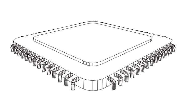
There is another important universal file format for PCB designs: STEP (Standard for the Exchange of Product). The need for a vendor-neutral file format for 3D mechanical models is described in the ISO 10303 standard. Currently, all major ECAD and MCAD software vendors support STEP files for electronic and mechanical components.
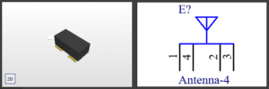
STEP model and schematic symbol for the Johanson Technology 2450AT07A0100T SMD chip antenna.
Why You Should Use Vendor-Neutral Symbols and Footprints
A file format like BXL and STEP files give designers everything they need to import important data into their ECAD projects. STEP models created in MCAD programs can be imported into a component library for use in an ECAD application. Similarly, a new PCB can be exported as a large STEP model and imported into an MCAD program, and a designer can create an accurate enclosure for a new product.
This all relies on finding the components you need for your new board. You’ll have to find vendor-specific files or BXL files for components to create symbols and footprints and you’ll have to find or make STEP files for components to create 3D CAD models. A parts search service is the best option as it can help you find CAD models, sourcing information, pricing, and lead times all in one place.
When you use a free service like Ultra Librarian, you won’t be limited to using the EPW file format with Library Loader. You’ll have immediate access to models for your components in your ECAD vendor’s file format. Ultra Librarian also offers an Online BXL Reader utility; you can take a home-made or vendor BXL file and convert it directly into supported CAD model formats quickly and easily. You can also edit BXL files in an accompanying desktop application. If you want to download components using a standard search engine, you’ll also have access to CAD models and sourcing information from worldwide distributors.
Creating, acquiring, and utilizing models from multiple file formats or creating design libraries requires most teams use dedicated resources and time. Ultra Librarian helps by providing the models you need from a single location. Working with Ultra Librarian sets up your team for success to ensure any design is going through production and validation with accurate models and footprints to work from. Register today for free!


