Vehicle electrification relies on many technological advances that span far beyond larger batteries and more efficient electric motors. The idea of electrification and making the electric grid “smarter” started over a decade ago and was regarded as something decades down the line. Now, renewable energy technologies and innovative power management systems can support vehicle electrification and at the same time help store excess power and use it at a later time when power is more sought for and priced higher.
Bidirectional power systems and modern power converter topologies drive true vehicle-to-grid (V2G) connectivity. The idea behind V2G is simple: create a bi-directional connection between a vehicle’s power system and the electric grid to enable efficient charging of electric vehicles and allow vehicles to pass excess power back to the grid. These systems carry some complex requirements, such as handling multiple voltage levels in a single unit while remaining stable in periods of peak demand.
Efficient storage and transfer of power between vehicles and the grid relies on highly efficient bidirectional DC/DC converters. Texas Instruments is helping designers accelerate innovation in this area with components and reference designs for bidirectional dual active bridge power converter topologies that support multiple output voltage levels. Keep reading to learn more about dual active bridge power converters and TI’s reference design (TIDA-010054) for level 3 electric vehicle charging stations.
The Role of Vehicles in V2G
Vehicles play an essential role in the V2G ecosystem because they spend so much time parked. If the power stored in a vehicle’s battery can be accessed during this time, it can be used to balance the grid. Advanced bidirectional DC/DC converters enable this type of interaction while also ensuring a car’s battery can be quickly charged when power is needed.
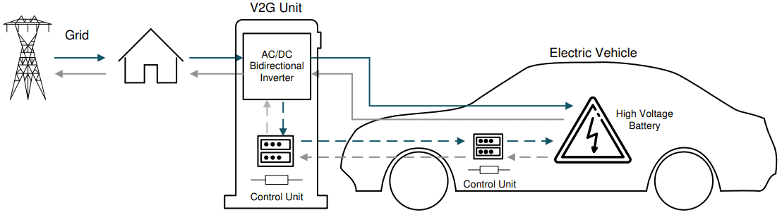
The role of vehicles in V2G [Source: TI Application note]
A DC/DC power converter provides the main power control and regulation functions used in EV charging stations and allows vehicles to interact with the grid. The most powerful stations are classified as Level 3 chargers, meaning they provide fast DC charging, with the capability of providing up to 20 miles per minute of range worth of charging.
In contrast, Level 1 and Level 2 chargers can provide up to approximately 30 miles of range per hour of charging. While Levels 1 and 2 rely on the onboard charger for AC-to-DC conversion from mains power, Level 3 charging involves connecting a car’s battery pack directly to a DC charging station providing 400V or 800V to the car battery.
Important trends being addressed in V2G-compatible DC/DC converters for Level 3 charging include dual-bridge topology implementation, use of wide bandgap semiconductors, shunt-based current sensing and real-time PWM control on each side of the converter.
Design Trends in DC/DC Converters for V2G
Multiple possible DC-DC converter topologies could be used for DC fast charging. These include:
- LLC resonant converter (half bridge or full bridge)
- Phase-shifted, full bridge
- Dual active bridge in CLLC mode
- Single-phase, dual active bridge
These converters have the broadest applicability while also providing bidirectionality as demanded in V2G applications.
GaN and SiC Semiconductors
Wide bandgap semiconductors like GaN LMG342xR030 and SiC FETs enable higher switching frequencies with lower resistive losses due to high electron mobility in these materials. These factors make bidirectional topologies more efficient than a comparable DC/DC converter with Si MOSFETs. These materials have additional advantages that make them useful in power systems, including no reverse recovery and lower overlap losses which helps improve power density.
Real-Time PWM Control and Zero-Voltage Switching
The C2000™ real-time microcontroller and UCC21759-Q1 gate driver in a dual-bridge DC/DC converter perform many tasks to ensure fast turn-on with low switching losses during operation. These tasks include tracking the power output via a feedback loop, applying a phase shift on each side of the converter to control power flow, and implementing zero-voltage switching.
With high resolution PWM control and power tracking, it is much easier to implement zero-voltage switching without bulky passive components, enabling lower switching losses and higher efficiency over a wider range.
About the TIDA-010054 Dual Active Bridge Reference Design
The TIDA-010054 from Texas Instruments is a dual active bridge reference design for a modular isolated DC/DC converter that facilitates bidirectional charging between the grid and an electric vehicle. The modular structure of this converter allows stacking in a single charging station to support higher power charging. It implements a best-in-class bidirectional symmetric topology that is demanded in V2G systems and technologies. The table below shows some of the main characteristics of the TIDA-010054.
| Input voltage range | 700 to 800 V DC |
| Output voltage range | 380 to 500 V DC |
| Output power rating | 10 kW maximum |
| Output current | 26 A maximum |
| Peak efficiency | – 98.2% at 6.6 kW
– 97.6% at 10 kW (full load) |
| Gate drive PWM frequency | 100 kHz |
| Power density | >2 kW/L |
| Output voltage ripple | Less than 5% |
| Input characteristics | 3-phase Vienna rectifier with power factor correction |
| Integrated control | Implemented with TMS320F280049 |
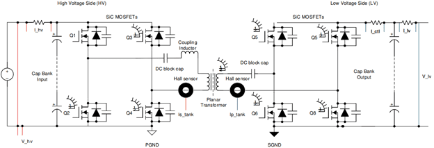
Structure and Topology
The overall topology of the device uses two full bridge stages on each side of a planar transformer, similar to an LLC converter but implemented to support bidirectional power flow. A planar transformer enables highly efficient power conversion at potentially very high PWM frequencies in a relatively low profile once the design is implemented in a production layout. In addition, the design implements SiC MOSFETs in the bridge circuits on each side of the device, which have lower losses and higher heat dissipation characteristics than Si MOSFETs.
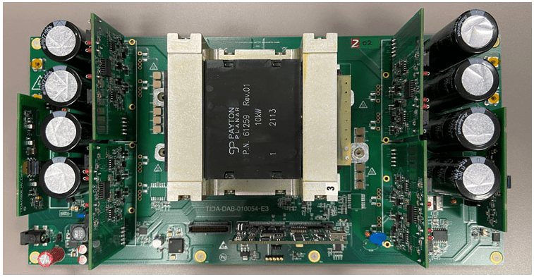
The reference design uses a sense card and two driver control cards on each side of the transformer to implement sensing, feedback and control over the full bridge circuits. The design uses the TMS320F280049 microcontroller, which provides real-time sensing with integrated ADCs, simplifies shunt-based current sensing, and allows fast control over high-frequency PWM signals. These control units also implement zero voltage switching to ensure low switching losses and low EMI during operation.
More resources for fast DC chargers
The TIDA-010054 provides an excellent starting point for advancing bidirectional charging systems for electric vehicles and V2G systems. Explore more design resources from Texas Instruments for fast DC chargers here.