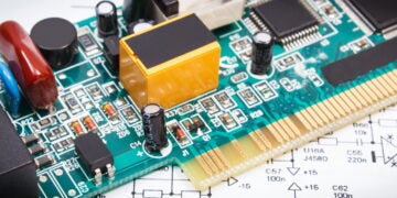
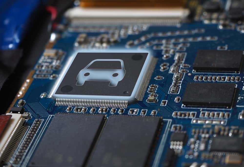
Vehicle systems are increasingly integrated with electronic PCBs
Only two decades into the twenty-first century electronics are critical parts of vehicle power trains. Digital gauge clusters and infotainment systems that interact with consumer electronics like phones, and diagnostic systems with sensor suites that can find and report mechanical issues are standard on many entry level vehicles. Sensor suites that can scan surroundings for threats and hazards, and even systems that interact with all of the previously mentioned electronics to drive the car autonomously are available on high end models, and may become the new standard within a decade.
All of these systems are enabled by off the shelf chips and electronic components mounted on printable circuit boards (PCB). Automotive PCB design guidelines play a critical role in ensuring the safe function of these systems, interoperability between different types of systems across brands, and optimization of design. Good automotive PCB design guidelines are the result of both common sense practices and the automotive pcb standards produced by industry and international bodies.
Basic Automotive PCB Design Guidelines and Practices
Automotive PCB design guidelines consider components, leads, and routing to ensure optimal results.
Automotive PCB design guidelines aren’t that different from PCB layout best practices for other industries. Many industrial environments have built-in sensors, diagnostic systems, and must be able to communicate information across many programs and apps that are tailored to specific purposes. The key difference in automotive systems is that they are consumer facing, and will operate in a mobile environment. This means safety and reliability of the PCB are going to be the key goal of automotive PCB design, and the guidelines that inform their design.
Orientation and Placement of Components
The most basic automotive PCB design guideline is component placement. Component orientation should simplify placement, and allow for efficient routing of leads. At the same time they should be far enough apart to minimize interference.
- Check for the appropriate spacing between components for the entire circuit board and individual layers. There are more in-depth component spacing guidelines for PCB design available.
- Separate analog and digital components to separate sections of the board.
- High power components should bedetailed component spacing guidelines kept separate from lower power components to better enhance heat dissipation.
- Similar components should be near each other and oriented in the same direction. This will make lead routing easier and facilitate soldering.
- For wave soldering this should be in the direction of the wave to prevent bridging or leaving circuits open.
- Inductors should be separated and placed at right angles to reduce crosstalk between them.
Power Supply, Grounding, and Lead Routing
Routing of the current throughout the board needs to balance the need for efficient routing: connecting points through the shortest possible route against the need to minimize interference by separating current flows.
- Provide wide spacing to separate power supply and ground lines
- Check for proper ground connections for both analog and digital circuits
- Leads should be separated to avoid interference due to coupling and inductance
- Verify layout connectivity with the desired connectivity when converting your schematics to PCB design layouts.
- The return current path should be placed near the main current path, but isolated from radiation to reduce the current loop area and improve circuit board performance.
Thermal Management
One of the most critical aspects in PCB design is thermal management. Excessive heat reduces the efficiency of components and performance of the electronic systems they are a part of. Truly excessive heat can physically damage the board. Automotive PCB design guidelines can account for thermal stresses by being aware of the following:
- Be aware of the thermal stresses PCB boards may be exposed to in operating environments.
- Provide heat sinks for high power components
- Place thermal pads under hot part of the board
- Use thermal pads and thermal vias to facilitate heat transfer to heat sinks or ground planes
In addition to these automotive PCB design guidelines that provide useful rules of thumbs to be mindful of through conception, design, and final manufacture of the automotive PCB there are also industrial standards to meet. These standards have less to do with design, and more to do with ensuring components and board materials meet minimum specifications to prevent faults and failures during manufacturing and final consumer operation.
Standards Governing Automotive PCB Design Guidelines

Interoperability and component reliability are major considerations for automotive electronic component standards.
Two of the most important standard making bodies for automotive PCBs are the AEC and IPC. The fist stands for Automotive Electronics Council (AEC) ; it was established by Chrysler, Ford, and General Motors in the 1990s. The second is the IPC, established in 1957 as the Institute of Printed Circuits but now just officially the IPC.
Standards from the AEC provide a wide array of testing and qualification regimes for integrated circuits, discrete semiconductors, sensors, and modules. In other words it is mostly concerned with the components that are mounted on the boards. Although it does provide some standards for board flex tests. IPC standard 6012 and revision D on the other hand concerns the fabrication of the boards themselves. With a special focus on cleanliness before, during, and after soldering.
On their own these standards are not automotive PCB design guidelines. However, they inform automotive PCB design in the components that meet these standards, and in ensuring that board designs are compliant during manufacturing processes. Designers can more easily meet these standards by combining good practices and automotive PCB design guidelines with a library of full specification CAD models from manufacturers that have tested their components to comply with ACE and IPC standards.
If you’re looking for CAD models for common components that comply with automotive PCB design guidelines working with Ultra Librarian sets up your team for success to ensure streamlined and error-free design, production, and sourcing. Register today for free.