MAX7219 provides data for efficiently driving LED displays
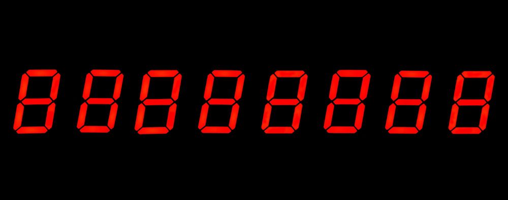
Eight-segment (including decimal point) LED displays are probably the most common electronic devices for communicating with users. These flexible components can be used to display graphics, convey textual information, or provide system status. Implementing these elements; however, requires LED drivers.
LED drivers range from simple ON/OFF control to more advanced functionality; such as brightness control. The MAX7219 is an example of the latter. To fully leverage the capabilities of this driver, an understanding of the wealth of design data given in the MAX7219 datasheet is required.
MAX7219: Features and Applications
The MAX7219 is a compact LED driver that often connects a microcontroller (MCU) or micoprocessor (MPU) to a display that provides important information to the user. These devices may be used in various systems that span across industries. This versatility is reflected in the listing of common applications below.
As discussed in the MAX7219 datasheet, this driver has a number of attractive features, as shown below.
Features of the MAX7219
- Digital brightness control
- Analog brightness control
- Data retention on low power shutdown
- Individual segment control
- Decode or No-Decode selection for each digit
- Common-Cathode LED displays
- Serial communication (10 MHz) protocol
- Dual package options: Dual in-line packaging (DIP) and small outline (SO) packaging
MAX7219: Architecture and Operation
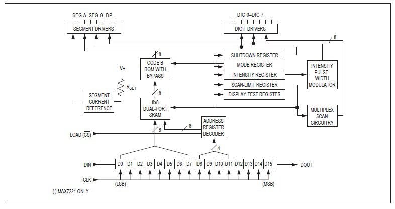
MAX7219 functional diagram
Many of the features of the MAX7219 can be visualized by examining the functional block diagram, shown above. For example, the device latches the serial input data line for load delivery with a delay of 16.5 clock cycles. And advanced functions, like intensity variation, are controllable by address encoding. Although operation is not complex, there are important design specifications provided in the MAX7219 datasheet that are critical to implementing the component in your design.
MAX7219: Important Design Specifications
When laying out boards with LED drivers, it is essential to follow PCB design best practices. These components typically must bridge high-performance parts like MCUs with output devices where layout and routing preferences may not be in agreement. Timing is also an important consideration on which the effectiveness of LED drivers rely. When formulating your design strategy, the most important attributes to rely upon are the electrical and thermal characteristics. These are presented below, following the MAX7219 pinout.
Pinout and Descriptions
As mentioned, the MAX7219 datasheet presents information on both the DIP and SO package options. Including the component pinout and descriptions, which are shown below.
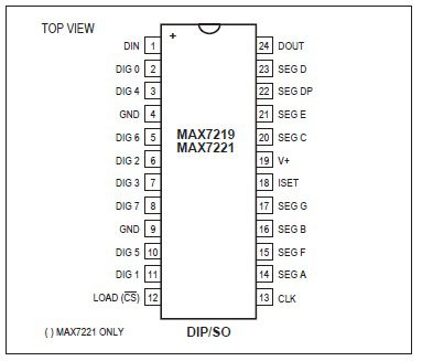
MAX7219 pinout
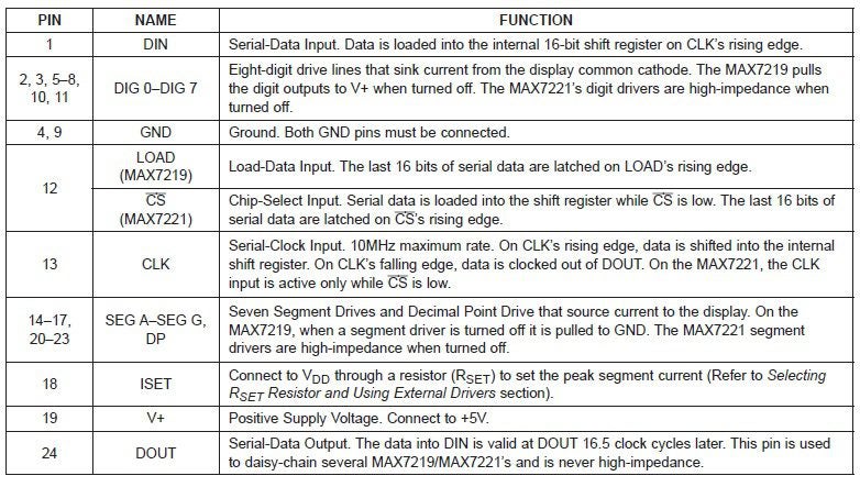
Pin descriptions for the MAX7219
The MAX7221, described in the pinout and pin descriptions above, includes additional capabilities not available with the MAX7219. These includes expanded communications options: SPI™, QSPI™, and MICROWIRE™ (SPI and QSPI are trademarks of Motorola, Inc. MICROWIRE is a trademark of National Semicoinductor Corporation).
Electrical and Thermal Characteristics
The parametric constraints that bound operational and performance objectives when implementing the MAX7219 are detailed below. These include the absolute electrical and thermal ratings listing, which also includes the maximum soldering temperature of 300°C. The logical specifications are also important to ensure the display is showing accurate information that is synchronized with system processing/operation.
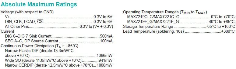
Maximum ratings for the MAX7219

Electrical characteristics of the MAX7219
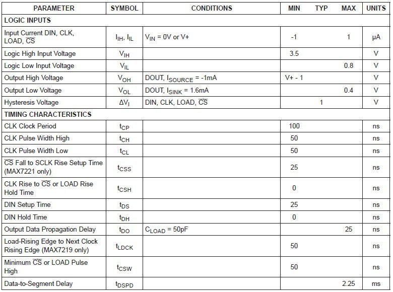
Logic and timing characteristics for the MAX7219
PCBA Design With the MAX7219 Datasheet
A typical circuit application using the MAX7219/MAX7221 is shown below.
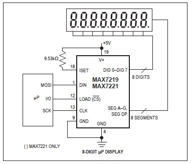
Typical implementation of the MAX7219
The MAX7219 datasheet also includes examples where multiple drivers are employed. These include a cascade example and a single driver-dual display configuration. Familiarity with the information provided in the datasheet is the first step to efficiently creating a successful design with the MAX7219. Equally important is the accuracy of the component CAD data, as shown below, that is used for your design
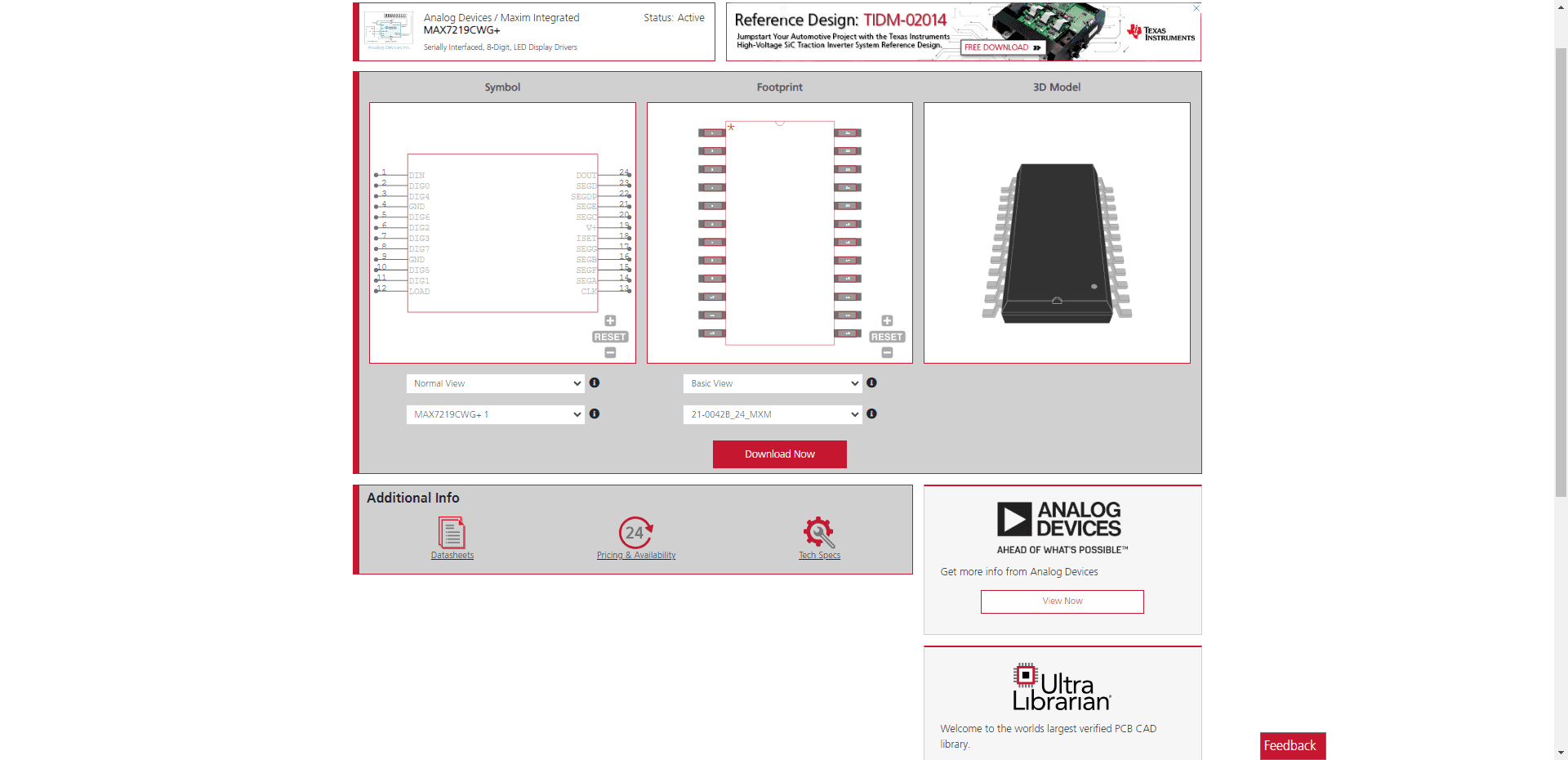
MAX7219 CAD model data from UL
If you’re looking for CAD models for common components or helpful information like how to best use the MAX7219 datasheet for your PCBA design, Ultra Librarian helps by compiling all your sourcing and CAD information in one place.
Working with Ultra Librarian sets up your team for success to ensure streamlined and error-free design, production, and sourcing. Register today for free.


")