
This simple component is the foundation for several op amp circuits that are implemented in a wide range of applications.
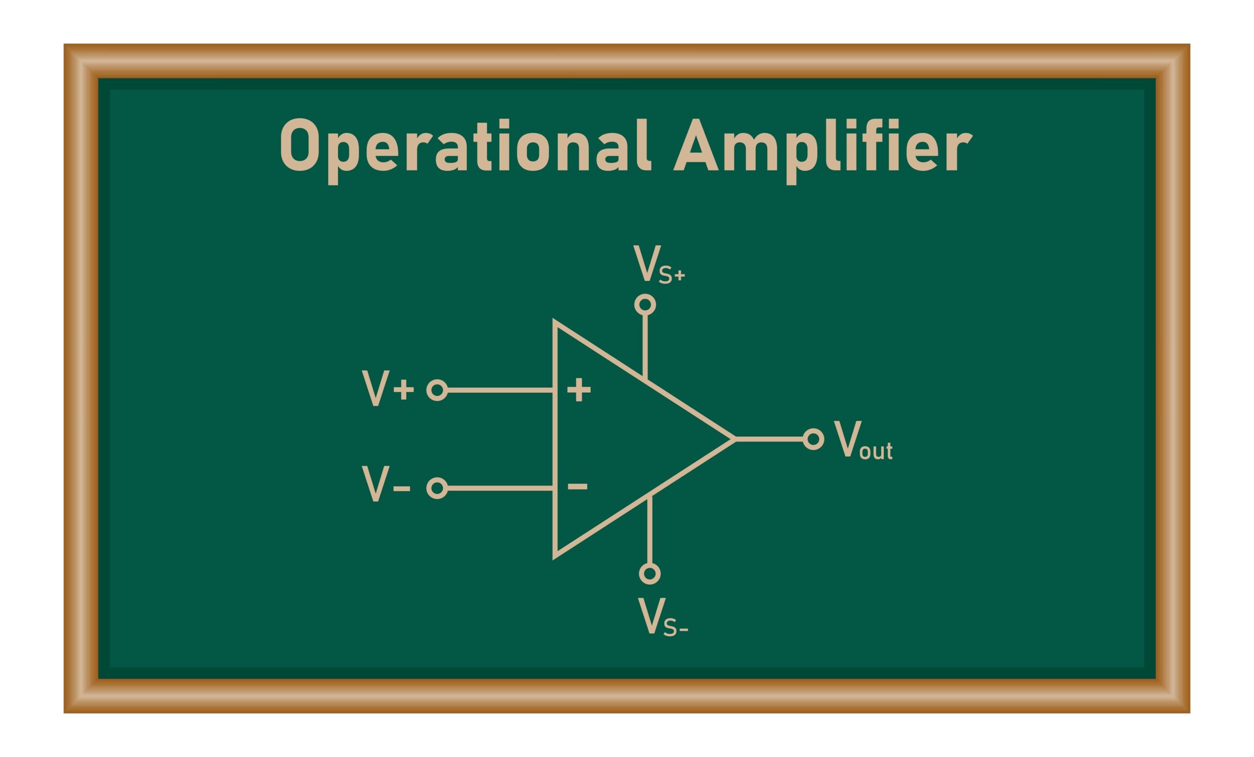
Analyzing operational amplifier (op amp) circuits effectively requires understanding a few fundamental principles that underlie how op amps behave in various configurations. Here are the basic rules for op amp analysis:
Basic Op Amp Circuit Configurations
Below, we’ve summarized some basic op amp circuit configurations.
Voltage Follower
The simplest op amp circuit configuration is as a voltage follower or voltage buffer. This circuit typically operates without the need for additional external components. It offers the advantage of having a high impedance at the input and a low impedance at the output, thereby serving as an effective buffer. The feature of a voltage follower is that the input and output voltages are identical, meaning any variation in the input voltage directly corresponds to a similar change in the output voltage.
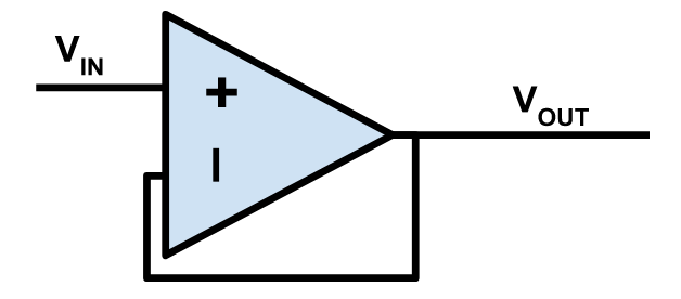
Basic op amp voltage buffer / voltage follower
Inverting Operational Amplifier
For inverting operational amplifiers, the operational amplifier works to ensure that the voltage at its negative terminal matches that of the positive terminal, which is often connected to the ground. As a result, the current entering the amplifier is governed by the ratio of the input voltage (VIN) to the resistance (R1). The output voltage is governed by VOUT = (R2/R1) * VIN
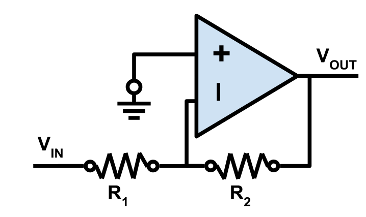
Op amp circuit inverting amplifier
Non-Inverting Op-Amp
In a non-inverting op amp circuit, the source’s input signal is linked to the non-inverting (+) input of the operational amplifier. This causes the operational amplifier to adjust the voltage at the inverting (-) terminal to match that of the input voltage, leading to a current through the feedback resistors. Consequently, the output voltage remains in phase with the input voltage, hence “non-inverting.” The voltage gain in a non-inverting amplifier setup is always higher than 1, a characteristic that distinguishes it from inverting configurations where this is not always the case. VOUT = (R2/R1) * VIN
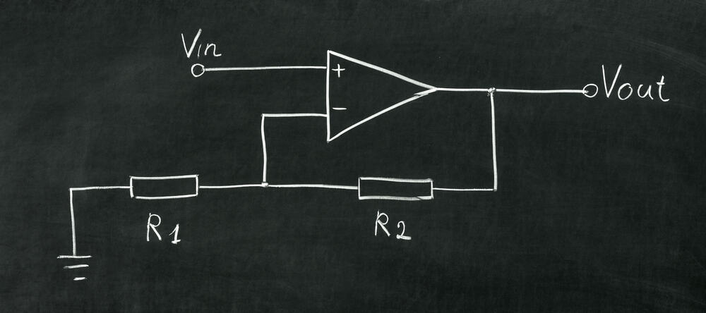
Non-inverting op amp configuration
Voltage Comparator
An operational amplifier configured as a voltage comparator is designed to analyze the voltages at its inputs, pushing its output to the voltage level of the supply rail corresponding to the higher input voltage. This setup operates in an open-loop mode due to the absence of feedback from the output to its input. One of the key advantages of voltage comparators over the closed-loop configurations previously mentioned is their ability to operate at significantly higher speeds.
In an open loop configuration, R1 is shorted and R2 is open-circuited. To add hysteresis, see the schematic below.
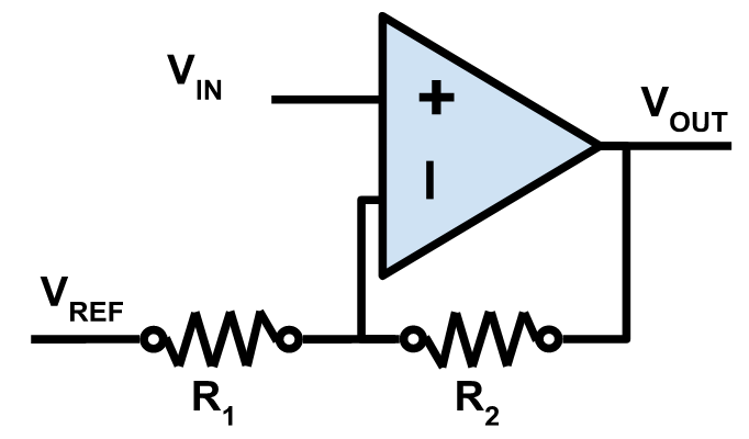
Op amp circuit for voltage comparitor with hysteresis.
Advanced Op Amp Circuit Topologies
In addition to the basic op amp circuit architectures above, these versatile components are used in many other applications. Notable more advanced op amp circuit topologies include the following:
- The summing amplifier configuration extends from the inverting amplifier design, featuring a virtual ground summing point, making it particularly suited for combining audio inputs. The advantage of the summing amplifier lies in its ability to prevent the mutual interference of different inputs, a feature attributed to the virtual ground summing point that maintains stability across varying input voltages and impedance levels.
- The subtractor, or differential amplifier, utilizes both inverting and non-inverting inputs. It generates an output signal representing the differential between two input voltages, V1 and V2, effectively allowing the subtraction of one signal from another. The design permits the addition of more inputs for further subtraction if necessary. When the resistances in the circuit are balanced (R=R3 and RA=R4), the output voltage achieves a specified value, with the voltage gain set at +1. Variations in input resistances can modify the circuit to amplify and yield either a negative output when V1 exceeds V2, or a positive output when V1 is less than V2, demonstrating the circuit’s flexibility in signal processing.
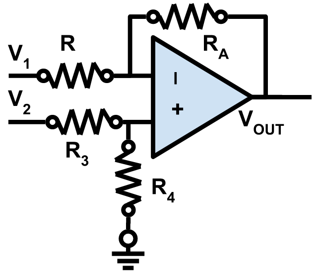
Subtractor op amp circuit (also known as differential amplifier)
- High-pass filters, including one, two, and three-pole configurations, using just a single op-amp can also be design. Adding a capacitor to the circuit allows for the straightforward creation of a single-pole circuit, while integrating the high-pass network into the feedback loop can significantly improve performance.
- For low-pass filter applications, operational amplifiers can also be used. By positioning a capacitor across the feedback resistor, a gentle roll-off can be achieved, with the breakpoint between the two components adjusted to produce the desired response.
- Bandpass filters, which only allow a specific range of frequencies to pass through, are capable of implementing active bandpass filter circuits for situations requiring a specific frequency band.
- Op-amp multivibrators that generate a square, rectangular, or pulse waveform (also called nonlinear oscillators or function generators) can also be created with op-amps, with numerous designs available online.
- In analog integrators, op-amps are perfectly suited due to their high input impedance and gain. This makes them ideal for integration applications, although very high input impedance chips may be necessary for prolonged integration periods.
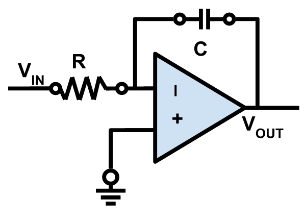
Op amp analog integrator
Unlock your design potential with Ultra Librarian, the go-to resource for electrical engineers and PCB designers seeking seamless integration with popular ECAD applications. Explore how to streamline your workflow and connect with global distributors effortlessly.
If you’re looking for CAD models for common components or important information to help you design op amp circuits, Ultra Librarian helps by compiling all your sourcing and CAD information in one place.
Working with Ultra Librarian sets up your team for success to ensure streamlined and error-free design, production, and sourcing. Register today for free.


")