

Amplification is one of an electronic circuit’s most basic yet critical functions. Amplifiers, however, are used to change signal amplitudes and many other signal-processing actions. BJTs, FETs, and MOSFETs often fulfill these requirements on circuit boards. Still, a wide range of operational amplifier applications remains due to these devices’ unique component characteristics and flexibility. Therefore, knowing how to best implement these amplifiers into your PCBA design is a much-needed skill.
Common Operational Amplifier Applications
Electronic amplification and amplifier can be broadly defined as follows:
Definitions:
Electronic amplification is the increase of a time-varying electrical signal’s voltage, current, and/or power.
An electronic amplifier is any device that uses an external power source to change the voltage, current and/or power of an electrical signal.
It is important to note that voltage and current may be changed by passing through many devices. Eddy current dissipation through passive devices like resistors is an example of this. However, an external source is required to increase or amplify signal power. This is true for active components, such as transistors, operational amplifiers, or OpAMPs. The latter of which is commonly used in the following configurations and applications.
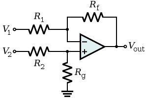
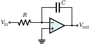
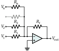
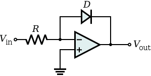
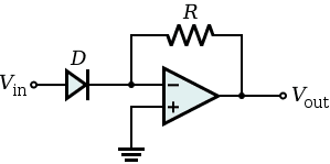
The versatility of operational amplifier amplification is demonstrated by the variety of configurations in the table above. Yet, OpAMPS are also used in specialized applications for oscillation, rectification, triggering, and resistance conversion. Regardless of the application or configuration, creating the best board design using OpAMPs means following good guidelines.
Optimizing Your OpAMP PCBA Design
In addition to many configurations, OpAMPs have different IC sizes to facilitate multiple component designs. Just as for single amplifier implementations, it is essential to use good guidelines, as listed below, to take full advantage of device properties and maximize PCBA design efficiency and effectiveness.
Operational Amplifier PCBA Design Guidelines
- Leveraging operational amplifier characteristics
OpAMPs possess certain unique characteristics that must be considered when implementing in your design. These include:
- Very high input resistance – no current flows into the device.
- Very low output impedance – minimal output current reduction.
- Very wide BW –any DC or AC signal can be amplified.
It is essential to note the above when researching your operational amplifier applications.
- Utilizing datasheets and support
The datasheet is the best source for your specific OpAMP’s characteristics. Other materials, such as sample utilization, case study results, and articles from trusted sources, can also be beneficial.
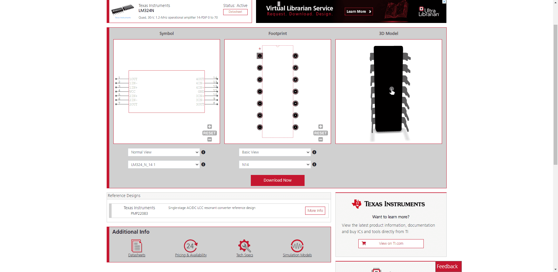
- Ensuring CAD model accuracy
It is imperative to source component design data, such as schematic symbols, footprints, 3D models, and other information, from a reliable source, as shown for the LM324 below.
Knowing typical operational amplifier applications and following design guidelines as listed above will help you optimize your OpAMP PCBA design and development.
If you’re looking for CAD models for common components or important design tips like how to optimize PCBAs for operational amplifier applications, Ultra Librarian helps by compiling all your sourcing and CAD information in one place.
Working with Ultra Librarian sets up your team for success to ensure streamlined and error-free design, production, and sourcing. Register today for free.


")
")