
Component Library Integration for Manufacturers: How Online Libraries Speed PCB Design

Are your parts hard to find in CAD tools? Verified component libraries cut placement time from 60 minutes to under 5 minutes with component library integration for manufacturers. Here’s how.
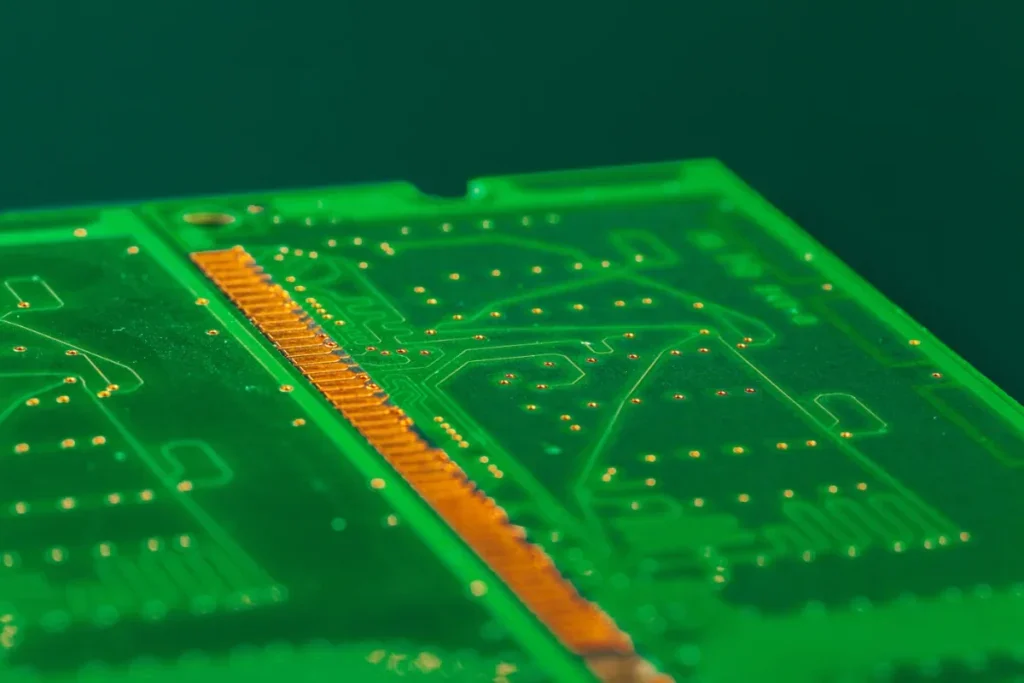
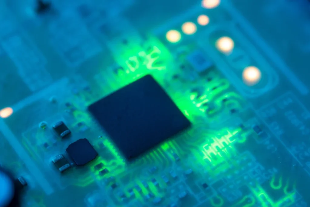
PCB Design for IoT Devices: Power, Connectivity, and Reliability Best Practices
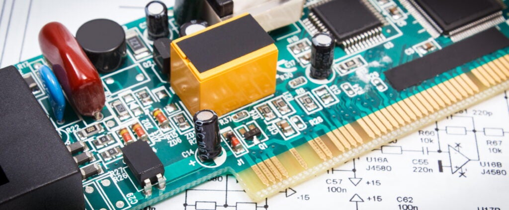
Illustration of PCB design development. The number of connected IoT devices is expected to grow 14% year over year to 22 billion by the end of 2026, with some analysts projecting it will reach around 39 billion by 2030. Every one of those devices needs a board that packs wireless radios, sensors, and a microcontroller […]
Aerospace PCB MIL-STD Requirements: What Designers Must Know
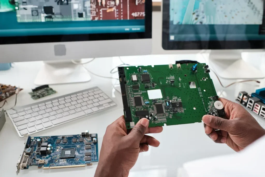
Learn aerospace PCB MIL-STD requirements with this guide to IPC Class 3 and MIL-PRF-31032 to ensure your flight hardware passes qualification testing.
Automotive PCB Design AEC-Q100: Ensuring Reliability and Compliance

A PCB’s reliability depends on proper automotive PCB design practices. Let’s start with a misconception that often trips up engineers new to vehicle electronics. There is simply no such thing as an “AEC-Q100 certified PCB.” The specification does not actually cover the fabrication of bare boards. When navigating Automotive PCB Design AEC-Q100 guidelines, remember that […]
PCB Impedance Control: The Key to Reliable High-Speed Circuit Design
Learn to configure PCB impedance control from scratch, including trace widths, dielectric constants, and stack-up geometry for high-speed boards.
PCB Thermal Management Techniques
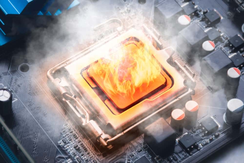
Is your high-power design running too hot to handle? Read up on PCB thermal management techniques to keep your electronics reliable.
IPC-2221 PCB Design Standards
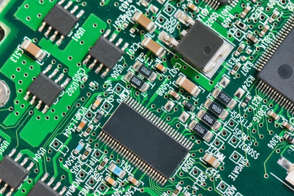
Learn how IPC-2221 PCB design standards define clearance, trace width, and reliability rules to ensure manufacturable, high-quality PCB layouts.
PCB Substrate Materials Comparison
Is your substrate a bottleneck? From FR4 to Rogers, see which material wins the fight for signal integrity in our PCB substrate materials comparison.
Power Management IC Design
Is your buck converter acting more like a radio transmitter? Learn how to control that noise and more power management IC design tips here.
High-Speed PCB Design Guidelines
Following High-Speed PCB Design Guidelines can help you avoid costly respins In the early days of electronics, printed circuit board (PCB) layout was often treated as “connecting the dots.” As long as the copper connected pin A to pin B, the circuit worked. Today, that approach is a recipe for failure. With modern processors, memory, […]