Finding the best PCB substrate material isn’t simple
In high-speed and high-power PCB design, the substrate is not just a mechanical surface holding components; it is an active circuit element. The dielectric constant (Dk) dictates propagation delay and impedance, while the dissipation factor (Df) defines signal attenuation. Similarly, the glass transition temperature (Tg) and coefficient of thermal expansion (CTE) are the primary predictors of mechanical failure in the field.
Most engineers stick to FR4 because it is cheap and familiar. But as designs push into the millimeter-wave spectrum (5G/radar) or demand kilowatt-level power handling, FR4 becomes a bottleneck.
This article presents a PCB substrate materials comparison to help you select the right material for your stack-up.
Material Properties Comparison
| Material Class | Typical Products | Dk (Dielectric Constant) | Df (Loss Tangent) | Thermal Cond. (W/m·K) | Tg (°C) | Z-Axis CTE (ppm/°C) | Relative Cost |
| Standard FR4 | Isola 370HR, Nanya NP-175 | 4.2 – 4.8 | ~0.02 | 0.3 – 0.4 | 130 – 180 | 50 – 70 (pre-Tg) | 1x (Baseline) |
| Rogers / High-Freq | RO4350B, RO3003 | 2.2 – 3.6 | 0.001 – 0.004 | 0.5 – 0.9 | >280 | 30 – 50 | 3x – 10x |
| Ceramics | Alumina (Al2O3), AlN | 9.0 – 10.0 | <0.001 | 24 – 200+ | N/A | 6 – 8 | 20x – 100x |
| Metal-Core (MCPCB) | Aluminum/ Copper Base | N/A (Dielectric dependent) | N/A | 1.0 – 4.0 (Dielectric) | >130 | Low (System level) | 2x – 5x |
| Polyimide | DuPont Kapton | 3.3 – 3.5 | 0.002 – 0.010 | 0.2 – 0.4 | >250 | 20 – 50 | High |
Technical Note: The Z-axis CTE is important for via reliability. Standard FR4 expands rapidly (often >200 ppm/°C) once it exceeds its Tg, acting like a hydraulic pump that can crack copper plating in plated through-holes (PTH). High-performance materials like Rogers RO4350B maintain a low Z-axis CTE (~32 ppm/°C), closely matching copper to prevent barrel cracks during reflow.
Detailed Material Analysis & Trade-Offs
FR4: The Mainstream Choice
FR4 (Flame Retardant Type 4) is a glass-reinforced epoxy laminate. It is the default choice for 90% of designs due to its excellent balance of manufacturability and cost.
- Trade-offs: FR4 has a high and frequency-dependent Dk (~0.02), making it unusable for long trace runs above 2–3 GHz due to attenuation. Its dielectric constant can vary significantly between batches, complicating impedance control for sensitive differential pairs.
- Best For: Consumer electronics, microcontrollers, IoT devices, and low-speed digital logic.
Rogers / PTFE Laminates: The RF Standard
“Rogers” is often used as a genericized trademark for high-frequency laminates, typically ceramic-filled PTFE or hydrocarbon composites.
- Signal Integrity: Materials such as RO4350B or RO3003 have an extremely flat Dk over a wide frequency range. This prevents “dispersion,” where different frequency components of a signal travel at different speeds, distorting digital pulses.
- Manufacturability: Pure PTFE is soft and difficult to drill (it can smear). However, ceramic-filled options (like the RO4000 series) process similarly to FR4, allowing standard fabrication lines to handle them without exotic plasma etching cycles.
- Best For: 77 GHz automotive radar, 5G antennas, RF power amplifiers.
Ceramics (Alumina & Aluminum Nitride)
Ceramics are most notable for their thermal management and performance in extreme environments.
- Thermal: Aluminum Nitride (AlN) boasts a thermal conductivity of 170–200 W/m·K—nearly 500x better than FR4. This makes it ideal for directly cooling high-power GaN (Gallium Nitride) transistors or laser diodes.
- Mechanical: They are extremely brittle. A ceramic board cannot withstand the flexing or vibration that an FR4 board handles easily. They also require specialized laser machining or thick-film processing.
- Best For: High-power LED modules, aerospace sensors, semiconductor packaging.
Metal-Core PCBs (MCPCB)
MCPCBs essentially glue a thin circuit layer onto a thick metal heat spreader (usually aluminum or copper).
- Heat Dissipation: While the dielectric layer is thin (~100µm) and thermally conductive, the real advantage is the metal backing, which dumps heat into a chassis or heatsink instantly.
- Limitations: You are generally limited to single-layer designs. Multilayer MCPCBs exist but are expensive and complex.
- Best For: LED lighting fixtures, motor drivers, and power converters.
Polyimide
Rounding out our PCB substrate materials comparison is polyimide, the standard for flexible and rigid-flex circuits.
- Flexibility: It can withstand millions of flex cycles without work-hardening the copper, provided the stack-up positions the conductor in a “neutral axis,” the region within the flex stack where bending-induced tensile and compressive stresses cancel out.
- Thermal: It has an incredibly high Tg (>250°C), withstanding environments that would char epoxy.
- Best For: Wearables, medical implants, military avionics (high vibration/heat).
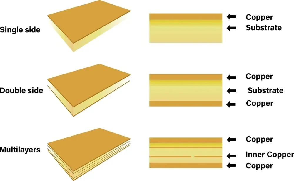
PCB construction options, but the choice of material may change depending on your project needs
Hybrid Stack-Ups: Getting the Best of Both Worlds
You don’t always need to build the entire board out of expensive Rogers material. A hybrid stack-up uses high-performance material for the signal layers (outer layers) and cheap FR4 for the mechanical core and power planes.
Example 4-Layer Hybrid Stack:
- Layer 1 (Signal): Rogers RO4350B (High speed, controlled impedance)
- Prepreg: FR4 (Bonding)
- Layer 2 (GND): FR4 Core
- Layer 3 (PWR): FR4 Core
- Layer 4 (Signal): Rogers RO4350B
Design Risks to Watch:
- CTE Mismatch: FR4 expands faster than Rogers. If the stack is unbalanced, the board will bow or twist during reflow. Always use a symmetric stack-up.
- Plasma Etching: Pure PTFE requires a specialized plasma cycle to prepare hole walls for plating. FR4 reacts differently to this plasma. Ensure your fab house has experience with “mixed-package” cycles to avoid uneven plating or “pink ring” defects.
PCB Substrate Materials Comparison Decision Checklist & Tools
When selecting a substrate, move beyond “cost vs. performance” and verify these specific parameters using the tools below.
Selection Checklist
- Frequency Check: Is your highest harmonic >1 GHz?
- No: Stick to High-Tg FR4 (Isola 370HR).
- Yes: Calculate loss. If attenuation > -10dB over the trace length, move to Rogers.
- Thermal Load: Is power density > 1 W/cm²?
- Yes: Consider Metal-Core or thick copper (>2oz) on FR4.
- Environment: Will the device see temperatures > 150°C?
- Yes: Polyimide or Ceramic is mandatory. Standard FR4 will delaminate.
- Mechanical: Does the board need to bend or fit a dynamic hinge?
- Yes: Polyimide (Kapton).
Recommended Vendor Tools
Don’t guess impedance. Use these validated calculators:
- Rogers Microwave Impedance Calculator (MWI): The gold standard for RF designs. It accounts for material roughness and frequency-dependent Dk.
- Saturn PCB Toolkit: Excellent free tool for via current capacity and low-frequency impedance checks.
- Sierra Circuits Material Selector: A handy online database to compare properties across brands (Isola vs. Panasonic vs. Rogers).
- Cadence Allegro Cross-Section Editor: If you use Cadence tools, load the specific dielectric materials from the library to simulate the exact stack-up behavior before you route a single trace.
Now that you have analyzed the trade-offs in this PCB substrate materials comparison, ensure your implementation is easy by using verified component models. Ultra Librarian gives you free access to millions of pre-built symbols, footprints, and 3D models from worldwide distributors, all ready for immediate export to popular ECAD applications.
Working with Ultra Librarian sets your team up for success, ensuring streamlined and error-free design, production, and sourcing. Register today for free.


")