Introduced over four decades ago, the LM317 remains one of the most popular and versatile three-terminal adjustable linear voltage regulators in the electronics industry. Capable of supplying more than 1.5A over an output voltage range of 1.25V to 37V, the LM317 is a staple in everything from hobbyist breadboards to industrial power supplies.
However, extracting reliable performance from this legacy component requires more than just connecting three pins. Thermal limits, dropout voltages, and minimum load requirements can easily trip up a design. By diving into the LM317 datasheet, designers can master its nuances. This guide breaks down the core specifications, essential formulas, application circuits, and layout guidelines needed to implement the LM317 successfully.
LM317 Datasheet: Key Specifications
Before designing a circuit, consult the absolute maximum ratings and typical operating conditions defined in the LM317 datasheet.
| Parameter | Value / Range | Engineering Relevance |
| Output Voltage Range | 1.25V to 37V | Highly adjustable using just two external resistors. |
| Output Current IOUT | 1.5A (Max) | Depends heavily on the package type (TO-220 vs. TO-92 vs. DPAK) and thermal management. |
| Input-to-Output Differential (VIN−VOUT) | 3V to 40V | Crucial: The LM317 is not a Low-Dropout (LDO) regulator. The input voltage must be at least ~3V higher than the desired output voltage. |
| Reference Voltage ( VREF) | 1.25V (Typical) | The internal voltage is maintained between the OUT and ADJ pins. |
| Minimum Load Current | 3.5mA to 10mA | The regulator requires a small continuous current drain to maintain regulation. |
LM317 Voltage Calculation and Formula
The LM317 regulates voltage by maintaining a constant 1.25V reference voltage between its Output (OUT) and Adjust (ADJ) terminals. By placing a resistor divider across these pins, you can program the output voltage.
The Output Voltage Formula:
VOUT = 1.25V x (1 + R2 / R1) + (IADJ x R2)
- R1: The programming resistor is tied between OUT and ADJ. A standard value is typically 240Ω or 330Ω. This value is chosen specifically to draw the required minimum load current (1.25V / 240Ω ≈ 5.2mA).
- R2: The adjustable resistor (or potentiometer) is tied from ADJ to ground.
- IADJ: The current flowing out of the ADJ pin (typically around 50µA). In most practical designs, the error introduced by (IADJ x R2) is small enough to be ignored.
If you want a 5V output, and you choose R1 = 240Ω:
5V = 1.25V x (1 + R2 / 240)
R2 = 720Ω
(Note: 720Ω is not a standard E12 resistor value; you would typically use a 680Ω resistor in series with a 39Ω or 47Ω resistor, or use a potentiometer to dial it in perfectly).
Practical Application Circuits
The versatility of the LM317 allows it to act as more than just a voltage regulator. Here are three common configurations found in the LM317 datasheet.
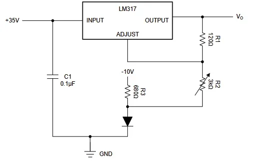
1. Basic Adjustable Voltage Regulator
This is the standard topology. It requires CIN (usually 0.1µF ceramic) to bypass high-frequency noise from the input supply. Here, the voltage is determined by:
- Formula: VOUT = VREF (1 + (R2 + R3) /R1) – 10 V
- By varying the voltage at the terminal of R3 (-10 V in diagram), VOUT is varied from 0V to 30V. In the absence of −10V, the VOUT is only regulated to the lowest value of VREF by making R2 = 0Ω.
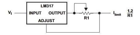
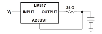
2. Precision Current Limiter (Constant Current Source)
By placing a single resistor (R1) between the OUT and ADJ pins and taking the load from the ADJ pin, the LM317 becomes a constant current source.
- Formula: IOUT = 1.25V / R1
- Application: Driving high-power LEDs safely or providing a constant current for battery charging. If R1 = 1.2Ω, the output current is capped at roughly 1A.
3. Constant-Current / Constant-Voltage Battery Charger
By combining the voltage divider of the standard regulator with a small current-sensing resistor, you can create a circuit that charges a battery at a constant current until it reaches a specific float voltage, at which point it acts as a constant voltage source. Make sure VI is greater than VBAT + 4.25V. (1.25V [VREF] + 3V [headroom])
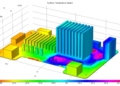
Efficiency and Thermal Management
One of the biggest pitfalls when designing with an LM317 is ignoring thermal dissipation. Because it is a linear regulator, it drops excess voltage by dissipating it as heat.
Efficiency Calculation
The efficiency of a linear regulator is essentially the ratio of output voltage to input voltage:
Efficiency ≈ (VOUT / VIN) x 100
If you are dropping 24V down to 5V, your efficiency is a dismal 20.8%. The remaining 79.2% of the power is converted to heat.
Power Dissipation and Heat Sinks
To calculate if you need a heat sink, calculate the Power Dissipation (PD):
PD = (VIN – VOUT) x ILOAD
If dropping 12V to 5V at 1A of current:
PD = (12V – 5V) x 1A = 7 Watts
Without a heat sink, a TO-220 package can typically dissipate only about 1 to 1.5 Watts before thermal shutdown occurs (when the internal junction temperature TJ exceeds 150°C).
To select a heat sink, use the thermal resistance formula:
TJ = TA + PD x (θJC + θCS + θSA)
Where:
- TA is the ambient temperature
- θJC is junction-to-case thermal resistance (from the datasheet)
- θCS is case-to-heatsink (thermal paste)
- θSA is the heatsink-to-ambient resistance you need to specify.
Comparing the LM317 to Modern Alternatives
While the LM317 is a classic, modern ICs offer specific advantages depending on the application.
| Feature | LM317 (Standard Linear) | AMS1117 (LDO) | LM2596 (Switching / Buck) |
| Topology | Linear (High Dropout) | Linear (Low Dropout) | Switching (Buck Converter) |
| Dropout Voltage | ~3.0V | ~1.1V | N/A (Duty Cycle Dependent) |
| Efficiency | Low (if VIN >> VOUT) | Low/Moderate | High (Up to 90%+) |
| Noise / Ripple | Very Low (Excellent for Audio/RF) | Low | High (Switching noise requires filtering) |
| External Parts | 2 Resistors, 2 Caps | 2 Resistors, 2 Caps | Inductor, Diode, Caps, Resistors |
| Best Use Case | Clean power, wide input range, and current limiting. | 5V to 3.3V step-down, space-constrained boards. | Large voltage step-downs (e.g., 24V to 5V) at high currents. |
Verdict: Use the LM317 when you need an exceptionally clean, low-noise power supply (like in audio amplifiers or analog sensor nodes) and have a few volts of headroom to spare. If you have a massive voltage drop, use a switching regulator to avoid melting your board.
PCB Layout Guidelines & CAD Models
When laying out the LM317 on a PCB, trace width and thermal management are your primary concerns.
- Trace Widths: Ensure the traces connected to the IN and OUT pins are wide enough to handle the maximum 1.5A current with minimal voltage drop.
- Thermal Pads: For surface-mount variants such as the DPAK (TO-252) or D2PAK, the large metal tab serves as the primary heat sink. It must be soldered to a large, unbroken copper pour (usually tied to the output voltage node, not ground). Use thermal vias to stitch this top-layer pour to the bottom-layer copper to increase the total dissipation area.
Common Design Mistakes and Troubleshooting
- Ignoring the Minimum Load: If the load connected to the LM317 draws less than ~5mA, the output voltage will float higher than calculated. Ensure R1 is 240Ω or less to satisfy this quiescent current requirement internally.
- Missing Protection Diodes: If you use a large output capacitor (e.g., >25µF), a short circuit on the input can cause the output capacitor to discharge backward through the LM317, destroying it. The datasheet recommends placing a 1N4002 diode reverse-biased across the input and output pins to provide a safe discharge path.
- Thermal Shutdown: If your output voltage suddenly drops to zero after a few seconds of heavy load, the chip is protecting itself. You need a larger heat sink, better PCB thermal relief, or a switching regulator.
An incorrect footprint, such as a DPAK footprint missing its thermal pad or with incorrect pad spacing, will result in immediate thermal failure or assembly issues.
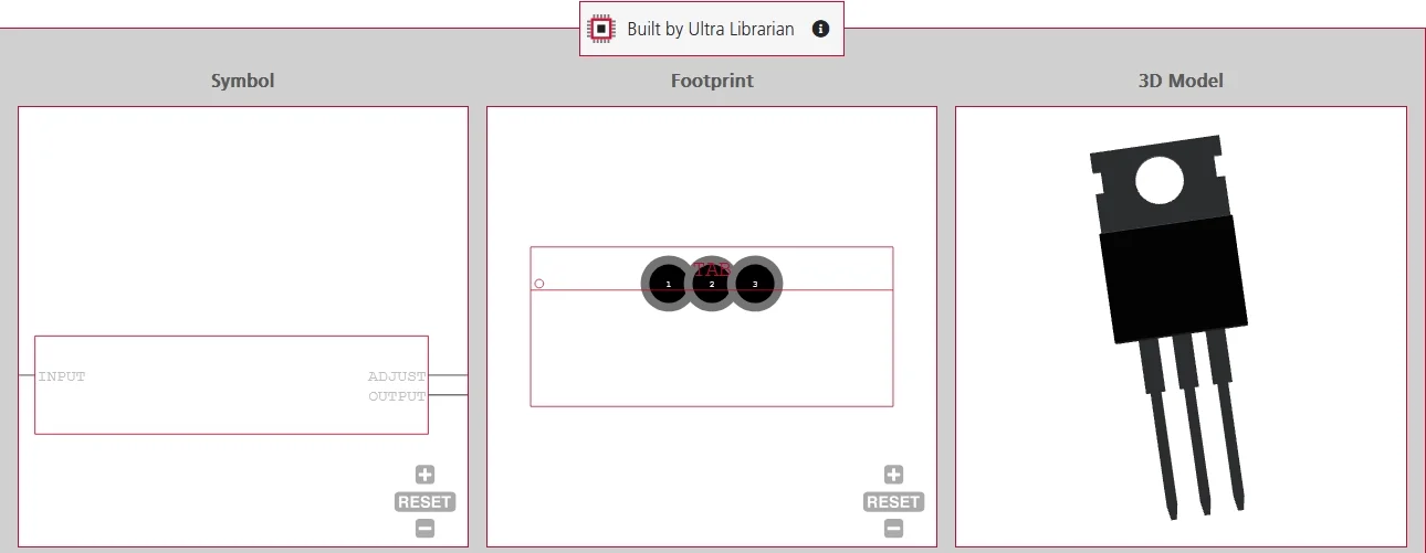
Don’t rely on generic, unverified footprints for critical power components. Ultra Librarian provides verified, IPC-compliant footprints, symbols, and 3D models for the LM317 (in TO-220, TO-92, DPAK, and more) supporting all popular ECAD applications, alongside real-time sourcing information from worldwide distributors.
Working with Ultra Librarian sets your team up for success, ensuring streamlined and error-free design, production, and sourcing. Register today for free.