

Let’s start with a misconception that often trips up engineers new to vehicle electronics. There is simply no such thing as an “AEC-Q100 certified PCB.” The specification does not actually cover the fabrication of bare boards. When navigating Automotive PCB Design AEC-Q100 guidelines, remember that the standard focuses solely on the reliability of integrated circuits packaged on the PCB. It treats these active parts as isolated items. You can place perfect silicon on a terribly routed layout. That board failure, however, falls entirely outside the scope of the AEC-Q100 document.
AEC-Q100 is formally titled “Failure Mechanism Based Stress Test Qualification for Integrated Circuits,” published by the Automotive Electronics Council (AEC). The standard applies strictly to packaged integrated circuits (ICs) — the active components mounted on the board, not the board itself.
AEC-Q100 is divided into 13 sub-standards: the main base document and 12 sub-standards numbered 001 through 012. Key qualification tests of AEC-Q100 include:
- Q100-001: Wire Bond Shear Test
- Q100-002: Human Body Model (HBM) Electrostatic Discharge (ESD) Test
- Q100-004: IC Latch-Up Test
- High-Temperature Operating Life (HTOL): Stress durations of 1,000 hours at the grade’s maximum ambient temperature: 150°C for Grade 0, 125°C for Grade 1, 105°C for Grade 2, and 85°C for Grade 3.
The objective of AEC-Q100 is to eliminate failures in a component’s early life and useful operating life, and to ensure that wear-out failures do not occur within the vehicle’s expected 10-to-15-year service life. Selecting the right grade for your application depends on where the component physically resides in the vehicle.
AEC-Q100 Temperature Grades by Vehicle Zone
| Grade | Ambient Temperature Range | Typical Application Zone |
| Grade 0 | -40°C to +150°C | Powertrain, Engine Control Units (ECUs) |
| Grade 1 | -40°C to +125°C | Under-hood environments |
| Grade 2 | -40°C to +105°C | Passenger compartment hot zones |
| Grade 3 | -40°C to +85°C | General cabin electronics |
As a rough guide, Grade 0 applications are typically under-hood, where ambient temperature specs can easily reach 105°C to 125°C. Grade 1 is typically used in-cabin or at chassis locations not directly exposed to heat from the engine, exhaust, or turbocharger.
Why AEC-Q100 Matters for Vehicle Safety
Commercial ICs are typically rated for 0°C to 85°C, with expected operating lives of 2–3 years and acceptable failure rates of 300 parts per million. Automotive requirements demand -40°C to 150°C operation, a lifespan of 10 years or more, and a failure rate of zero. Standard commercial silicon is not packaged or tested to survive those conditions, and its use would result in accelerated electromigration and solder joint fatigue long before the vehicle’s useful life ends.
AEC-Q100 qualification also underpins compliance with ISO 26262, the international functional safety standard for road vehicle electronics. Using qualified parts ensures the baseline reliability metrics used to calculate safety integrity levels remain valid. ISO 26262 defines risk through Automotive Safety Integrity Levels (ASILs):
- ASIL A: Lowest risk level, for non-critical systems
- ASIL B & C: Low-to-medium risk systems such as dashboard displays and camera modules
- ASIL D: Highest risk level — steering, braking, and Advanced Driver Assistance Systems (ADAS) — requiring extreme redundancy
Placing commercial-grade silicon in an ASIL D braking module introduces failure probabilities that no amount of system-level redundancy can fully compensate for. AEC-Q100 qualified parts give you the statistical foundation to build those calculations on solid ground.
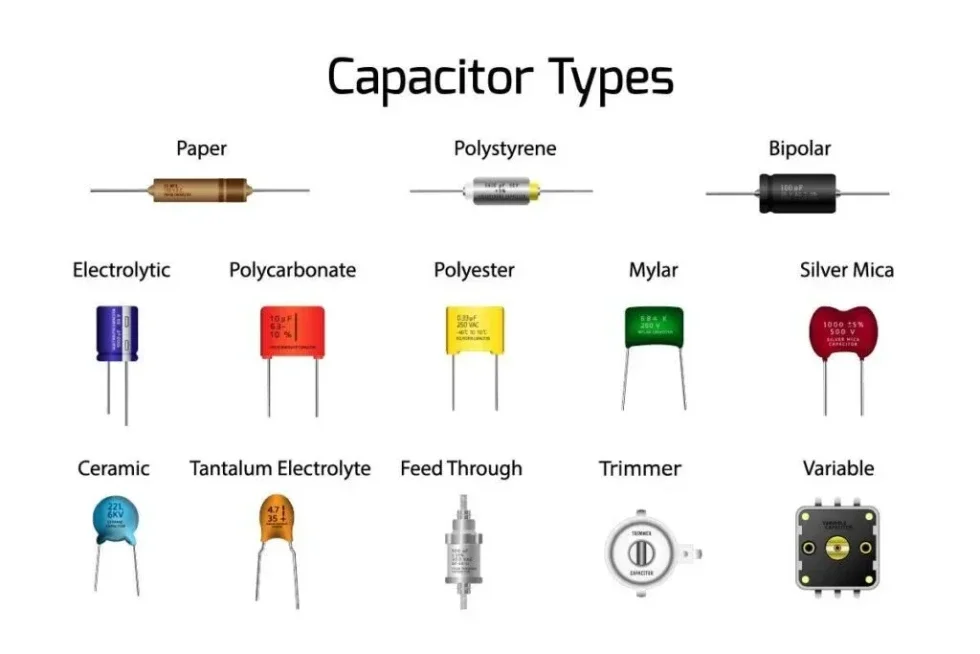
An automotive bill of materials requires attention to both active ICs and passive components, like capacitors
AEC-Q200 and Passive Component Qualification
One more thing worth noting: AEC-Q100 covers active ICs, but a complete automotive bill of materials (BOM) also requires attention to passives. AEC-Q200 is the Automotive Electronics Council’s qualification specification for passive components, including capacitors, resistors, inductors, transformers, crystals, and fuses. Compliance testing for these parts proves they can withstand and continue to perform in a vehicle throughout its life. If a passive component is not AEC-Q200 qualified, it is not automotive-grade.
Automotive PCB Design AEC-Q100: Board-Level Considerations
Specifying a Grade 0 microcontroller means nothing if the board beneath it cracks first. You have to consider the complete physical assembly. A successful approach to Automotive PCB Design AEC-Q100 integration dictates that your layout choices must physically shield those ICs. You are actively protecting them against the exact same environmental hazards, like extreme engine heat and severe mechanical shock, that they faced during their initial lab testing.
Thermal Management for Extreme Operating Temperatures
Grade 0 ICs operate at up to 150°C ambient temperature, and localized hot spots can push junction temperatures well past the absolute maximum ratings. It is imperative to design the board to move heat away aggressively using the following strategies:
- Place solid-filled thermal vias directly beneath high-power components to conduct heat into internal copper planes
- Use 2 oz or 3 oz copper pours on power and ground planes to distribute heat across the board structure
- Physically separate sensitive analog circuitry from high-heat digital processors and power supply management ICs to prevent thermal coupling
Vibration Resistance
Vibration causes solder joint fatigue. Designers mitigate this by using smaller components, adding mechanical support, and applying teardrops on all pad-to-trace junctions. Beyond that:
- Avoid placing tall, heavy components, such as aluminum electrolytic capacitors, adjacent to fine-pitch ICs. Vibration-induced mechanical stress on neighboring pads is a common failure mode
- Add mounting holes and structural supports near heavy component clusters
- Apply conformal coating or potting compounds for assemblies exposed to severe vibration near the drivetrain or axles
Substrate Material Selection
Standard FR-4 with a glass transition temperature (Tg) of 130°C is inadequate for high-heat automotive environments. Once board temperature exceeds the Tg, the substrate expands rapidly along the Z-axis, tearing via barrel plating from the inside. Match your substrate to the operating environment:
- High-Tg FR-4 (Tg > 170°C): Sufficient for most under-hood applications
- Polyimide: For extreme-temperature flex circuits routed through tight mechanical spaces
- Metal Core PCBs (MCPCBs): For LED headlamp systems and high-current power inverters, where heat must be conducted away from components immediately
Assembly, Manufacturing, and Supply Chain Compliance
Designing the board correctly is essential, but you aren’t done yet. You must also enforce the standards at the fabrication and assembly stage, and control the supply chain feeding into it.
Board Fabrication Standards
IPC-6012 and its automotive addendum, IPC-6012DA, form the foundation for manufacturing and acceptance of automotive PCBs. These standards impose requirements that far exceed standard industrial grades, specifically Class 3 or higher, for dimensions, plating, via copper thickness, dielectric layers, and surface finishes. Specify the following on your manufacturing drawings:
- IPC-6012 Class 3: Requires higher plating thicknesses in via barrels and prohibits voids or breakouts in annular rings
- IPC-6012DA: The automotive addendum identifies automotive performance classes, sustainability and reliability testing requirements, and solder mask thickness coverage over conductors, planes, and adjacent surface mount devices. It also adds tighter requirements for hole position and pattern feature accuracy
- IPC-A-610 Class 3: Governs the acceptability of finished soldered assemblies, covering solder wetting quality and joint volume
Supply Chain Traceability
Counterfeit components are a real and well-documented risk in automotive supply chains. Procure all AEC-Q100- and AEC-Q200-qualified parts exclusively through franchised distributors that can provide full lot traceability back to the original semiconductor manufacturer. A part with no verifiable provenance is a liability, regardless of what the label says.
Manufacturing Partner Certification
Not every contract manufacturer is equipped for automotive work. Verify your manufacturing partner meets these requirements before placing an order:
- IATF 16949 certification: The global quality management standard for automotive production, requiring strict traceability controls, Advanced Product Quality Planning (APQP), and formal risk management processes
- Automated Optical Inspection (AOI): Required for all surface-mount assemblies to catch placement and soldering defects before they leave the line
- X-ray inspection: Mandatory for ball grid array (BGA) packages where solder joints are hidden beneath the component body and cannot be visually verified
The laboratory performing any AEC-Q100 or AEC-Q200 qualification or test work must also be ISO 17025:2017 certified.
Automotive electronics demand that every layer of the design stack, including component qualification, board fabrication, assembly process, and supply chain, be held to the same standard. AEC-Q100 sets the floor for your active components. Everything else is your job to specify.
Ready to build highly reliable vehicle systems? Moving from component selection directly into board layout gets much easier when you rely on accurate CAD models. Nailing your Automotive PCB Design AEC-Q100 requirements demands a solid foundation of verified data. Ultra Librarian provides a massive library of qualified parts, easily exported to popular ECAD applications, and sourced from worldwide distributors to ensure your high-speed design and supply chain remain secure from day one.
Working with Ultra Librarian sets your team up for success, ensuring streamlined and error-free design, production, and sourcing. Register today for free.


")
")

