Far too often, it is incorrectly assumed that learning how to choose the right capacitor is as simple as matching voltage and current requirements. Another misconception is that exceeding a capacitor’s voltage rating will cause the device to fail. Here’s the short answer: choosing the right capacitor comes down to nine key factors, including dielectric properties, temperature rating, ESR, resonance, dissipation factor, DC biasing, tolerance, polarization, and size.
Knowing how to choose the right capacitor for your design requires understanding how these parts work and taking several design factors into account. Understanding these factors will ensure your circuit performs as designed and help you avoid unexpected operational failures once your board is deployed.
How to Choose the Right Capacitor: Essential Factors
Capacitors are relatively simple passive electronic components. However, they perform several critical functions for electronic circuits. These functions include decoupling, filtering, power supply conversion, impedance matching, grounding efficiency, and minimizing electromagnetic interference (EMI). Although voltage and current ratings are important when choosing a capacitor, other factors will influence how capacitors will function in your circuit and should be considered as well.
Capacitors and Essential Factors
| Factor | Description |
| Dielectric Properties | Capacitance is determined by the dielectric properties of the material used for its construction. |
| Temperature | The environment the capacitor can operate in is limited. Consequently, temperature is an important consideration, especially in automotive, industrial, and other hazardous applications. |
| ESR | ESR varies with frequency, which makes this a critically important factor for radio frequency (RF) circuit implementation. |
| Resonance | Capacitance balances inductance to achieve resonance, which is essential to maximize signal power transfer and match impedance. |
| Dissipation Factor | The rate of signal or charge loss. |
| DC Biasing | Capacitance will change with the application of a direct current (DC) supply. |
| Tolerance | The minimal and maximum range of variation from the ideal for the actual physical capacitor. |
| Polarization | Some capacitors are polarized or can only be used for current flow in one direction. |
| Size | An undervalued consideration that can be significantly impactful for manufacturing and for electronic computer-aided design/mechanical computer-aided design (ECAD/MCAD) integration. |
Dielectric Properties
The capacitance can be calculated using the formula:
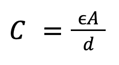
Where;
- C= capacitance
- 𝞊 = dielectric permittivity
- A = Plate area in sq meters
- d = distance between plates in meters
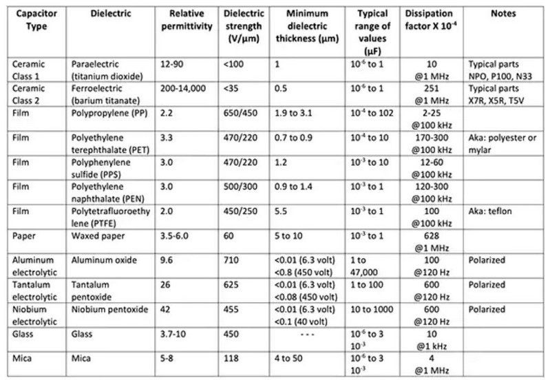
Choosing capacitors with high dielectric strength offers high capacitance. The table below shows characteristics of common capacitor types, sorted by dielectric materials.
Temperature
Every capacitor has a specific operating temperature range specified on the package. Beyond that temperature limit, the insulation around the dielectric starts to degrade and may cause electrolyte loss and leakage current. Here is a quick comparison of three popular types of capacitors based on their maximum operating temperature.
Capacitor Temperature Range Comparison
| Capacitor Type | Min. Temperature | Max. Temperature |
| Aluminum Electrolytic | -55 ℃ | 150 ℃* |
| Film | -55 ℃ | 105 ℃ |
| Ceramic | -55 ℃ | 125 ℃ |
*150 ℃ (automatotive/high-temp grade; standard commercial grade: 85-105℃).
Selecting a capacitor that can safely operate under the maximum operating temperature of the application is always imperative.
Equivalent Series Resistance
Engineers are often surprised to learn that the equivalent circuit of a capacitor includes an equivalent series resistance (ESR) and an equivalent series inductance (ESL). The internal resistance is due to the materials, design, and manufacturing process.
The value of ESR changes with a change in frequency. At low frequency, the ESR value is very high and decreases with the increase in frequency and also changes with temperature.
The mathematical expression is as follows:
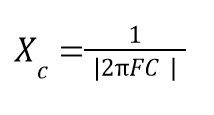
Here, XC represents the capacitive reactance, including ESR and ESL. The value is inversely proportional to the operating frequency. Terms F and C represent frequency and capacitance, respectively.
At high frequency, that means the capacitor offers the easiest path to the current flow. Thus, capacitors with low ESR values are always preferred. Make sure to check the datasheet to confirm the best temperature and frequency combination to operate the capacitor at the lowest ESR value possible. Usually, the ESR of electrolytic capacitors is the highest, whereas that of film capacitors is the lowest. Ultra Librarian makes it easy to access and compare component datasheets across manufacturers, cutting out the usual cross-referencing work.
Resonance
There is always a reduction in the power of a signal when it travels through a capacitor. This is known as insertion loss. In an ideal capacitor, the capacitance increases with increasing frequency. However, in an actual capacitor, the loss increases until the capacitor attains its self-resonance frequency (the frequency at which impedance becomes zero) and then decreases.
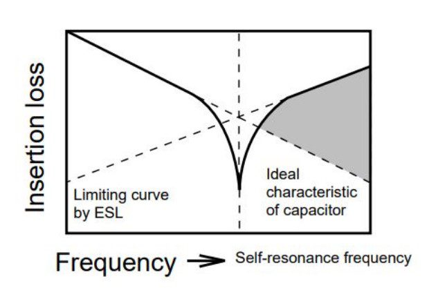
This concept is used to reduce the noise signal of a capacitor until it hits the self-resonant frequency. As a result, in a high-frequency range, go with capacitors that have a high self-resonance frequency (or low ESL value) for better noise suppression.
Dissipation Factor (DF)
Now that we know capacitors have internal resistance, it makes sense that some power is lost when an alternating current (AC) voltage is applied. This rate of loss is known as the dissipation factor.
The mathematical expression is as follows:
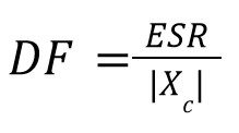
Here, DF represents the dissipation factor.
If you look at the datasheet for any capacitor, you will notice that at a particular operating temperature and frequency, the capacitor has different DF values across different stages of rated voltage. Consult your contract manufacturer (CM) to help you select the best capacitor for your application with the lowest DF possible.
DC Biasing
The capacitance rating noted on a capacitor’s datasheet is under ideal conditions without any DC supply. However, if you are considering a ceramic capacitor with a high dielectric constant, under practical application scenarios, a small DC supply can change the capacitance value. That’s called DC biasing. Under such circumstances, you have three options for capacitor selection with a significant DC biasing effect:
- Go for a high capacitance value
- Use a physically larger package size
- Switch to a different type
Tolerance
The tolerance value represents the minimum and the maximum range of a capacitor from its nominal value. For example, a 1,000 µF capacitor with ±1.5% tolerance value can be used in 985 µF – 1,015 µF applications. For sensitive applications such as timing elements, low-tolerance capacitors are preferred. However, coupling capacitors have a wide tolerance to allow even the lowest frequencies with ease. Tolerance is just one factor of how to choose the right capacitor, and polarization is another that can make or break your design.
Polarization
Polarized capacitors (P-C) are used across the voltage in a certain polarity. The negative terminal has a negative symbol over the surface of the capacitor and has a smaller lead than the positive terminal. Aluminum electrolytic capacitors are polar capacitors and come with two leads of different lengths.
On the other hand, non-polar capacitors (N-P-C) can be connected either way in a circuit design. Similarly, ceramic capacitors and film capacitors are non-polar.
P-Cs offer a large capacitance value in a tiny package. They also cost significantly less than N-P-Cs for the same capacitance and voltage ratings. However, a P-C has a large leakage current and cannot operate at higher frequencies like an N-P-C can. While a P-C finds its major application in DC circuits, N-P-Cs can be used in both AC and DC, and at low or high frequencies.
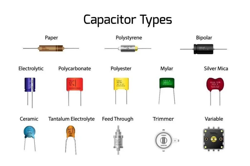
The table below shows the types of capacitors and their area of application.
Common Capacitor Types, Characteristics, and Typical Applications
| Types | Characteristics | Applications |
| Ceramic | Power capacitors High precision Non-polarized | Resonant circuits in transmitters DC motor to reduce noise |
| Electrolytic | Wide tolerance High capacitance High ESR Polarized | Filtering circuit Switched-mode power supply (SMPS) Low-pass filters |
| Tantalum | High tolerance Low leakage current Low max operating voltage Good stability Polarized | SMPS Sample and hold circuits Military applications |
| Film | Good stability Low inductance Long shelf life Non-polarized | Phase shifting Power factor (PF) correction Analog-to-digital (A/D) converters Decouplers |
| Silver Mica | Low capacitance High stability High voltage Non-polarized | RF circuits Oscillators |
Size
SMD (surface-mount device) capacitors offer a low-cost, high-capacitance-to-footprint ratio with minimal parasitic inductance, which is ideal for designing high-frequency or high-speed circuits. However, when it comes to reliability under harsh environments, through-hole capacitors are best. The mechanical bonding is stronger with through-hole capacitors than with their SMD counterparts because they are soldered deep within the board layers.
There are four popularly used through-hole capacitors:
- Film capacitors
- Ceramic capacitor
- Aluminum electrolytic capacitor
- Aluminum polymer capacitor
Amongst these four, the film capacitor has the widest footprint (2.5 cm long), whereas the ceramic capacitor has the minimum (<5 mm long). The electrolytic capacitor is narrower and longer, while the polymer one is shorter and fatter.
Through-hole electrolytic capacitors are widely used in aerospace and military applications. They are also best for prototyping and testing.
Optimizing Your Capacitor Selection Process
The best way to optimize your selection of capacitors and other components is to easily compare them without needing to perform costly cross-referencing across different sources. Ultra Librarian and DigiKey have partnered to create UltraBOM®, which allows you to do head-to-head comparisons on real-time data. Once you select the right capacitor for your design, you will need accurate printed circuit board (PCB) footprints, schematic symbols, verified computer-aided design (CAD) models, and more. Ultra Librarian is the best resource for these design essentials, and to expedite procurement, you can order parts directly from DigiKey in your electronic design automation (EDA) tool.
If you’re looking for CAD models for common components or the most essential information on how to choose the right capacitor, Ultra Librarian pulls all your sourcing and design data into one place, so your team can stop digging through tabs and start designing.
PCB designers who work with Ultra Librarian set their teams up for success, ensuring streamlined and error-free design, production, and sourcing. Register today for free.

 If you’re looking for any of our component footprints or models, we have readily available and free options for you and your design team. Search our library for the solution you’ve been looking for.