Single-cell Li-ion and Li-Po batteries require controlled constant-current/constant-voltage charging. These cells typically have a nominal voltage of about 3.6–3.7 V and are charged to a maximum of 4.2 V. The TP4056 is a linear charger designed to manage this charging process, with programmable charge current, thermal regulation, charge termination, and temperature monitoring. The TP4056 datasheet also covers the typical application circuit, charge current programming, and thermal regulation. The TP4056 itself does not provide battery protection or input-current limiting, so those are up to you.
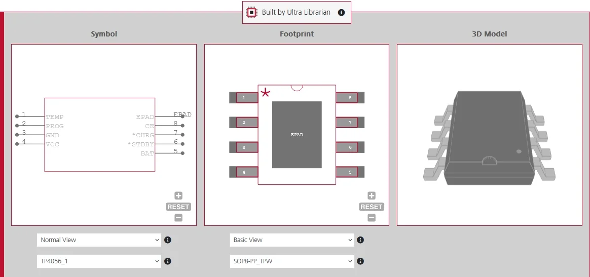
TP4056 Pinout in the Small Outline Package (SOP-8)
The TP4056 is commonly supplied in an 8-pin SOP.
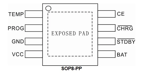
TP4056 Pinout
| Pin | Name | Function |
| 1 | TEMP | Battery-temperature sensing input for an external thermistor network. |
| 2 | PROG | Sets the charge current with an external resistor and can monitor charge current. |
| 3 | GND | Ground connection. |
| 4 | VCC | Positive input-supply connection. |
| 5 | BAT | Battery charging and voltage-sensing connection. |
| 6 | STDBY | Open-drain charge-complete status output. |
| 7 | CHRG | Open-drain active-charging status output. |
| 8 | CE | Chip-enable input used to enable or suspend charging. |
VCC, BAT, and GND carry the main charging current, so these connections should use short, low-resistance printed circuit board (PCB) traces or copper pours.
Charging Modes in the TP4056 Datasheet
The TP4056 automatically moves through several charging stages according to battery voltage and charge current. The charging states include trickle charging, constant-current charging, constant-voltage charging, charge termination, and automatic recharge.
Trickle Charge
If the battery voltage is below approximately 2.9 V, the TP4056 applies a reduced trickle-charge current to safely recover a deeply discharged cell. The normal charging current is set by RPROG, an external resistor connected to the PROG pin; changing this resistor adjusts the programmed charge current. For example, with RPROG = 1.2 kΩ, the normal charge current is about 1 A, while the trickle-charge current is approximately 100 mA. Once the battery rises above about 2.9 V, the charger transitions to constant-current operation.
Constant-Current Charging
During constant-current charging, the TP4056 supplies the programmed charge current while the battery voltage rises toward 4.2 V. For example, with RPROG = 1.2 kΩ, the charger supplies approximately 1 A during this stage, subject to input-power and thermal limits.
Constant-Voltage Charging
As the battery approaches 4.2 V, the TP4056 transitions to constant-voltage regulation. The charger holds the battery near 4.2 V while the charging current gradually decreases as the cell approaches full charge.
Charge Termination
Charging terminates when the current falls to roughly one-tenth of the programmed value during constant-voltage operation. For example, with a programmed current of 1 A, termination occurs at approximately 100 mA.
Automatic Recharge
After charging terminates, the TP4056 continues monitoring the battery. If the cell voltage falls approximately 150 mV below the 4.2 V regulation voltage, to around 4.05 V, the charger automatically begins another charging cycle.
Setting Charge Current with the PROG Resistor
A resistor between PROG and ground determines the TP4056’s maximum constant charge current. A useful approximation is:
IBAT (mA) ≈ 1,200 / RPROG (kΩ)
A 1.2 kΩ resistor therefore provides approximately 1 A. Increasing the resistance reduces the current.
Common TP4056 Charge-Current Settings
| RPROG | Approximate Charge Current |
| 10 kΩ | 120 mA |
| 5 kΩ | 240 mA |
| 3 kΩ | 400 mA |
| 2 kΩ | 600 mA |
| 1.5 kΩ | 800 mA |
| 1.2 kΩ | 1,000 mA |
A 1.2 kΩ resistor is common on inexpensive boards using the TP4056 charging module, but designers should not automatically use the maximum 1 A setting. The correct value depends on the battery manufacturer’s permitted charge rate. For example, if a 1,000 mAh Li-Po cell is rated for a maximum 0.5C charge rate, its maximum recommended charging current is 500 mA. An RPROG value of about 2.4 kΩ would set the TP4056 charge current to approximately 500 mA rather than 1 A.
TP4056 Reference Charging Circuit
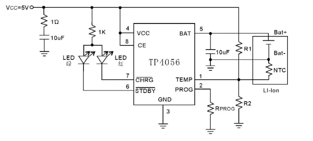
A basic single-cell TP4056 circuit requires only a small number of external components, which is one reason the device is common in compact battery-powered designs. The reference circuit above from the TP4056 datasheet shows the TP4056 charging a single Li-ion cell from a 5 V supply while RPROG sets the charge current. The CHRG and STDBY outputs drive status LEDs, and the negative temperature coefficient (NTC) thermistor network connected to TEMP allows charging to pause if the battery temperature moves outside the permitted range.
Core Connections for a TP4056 Charging Circuit
The main charging path is straightforward:
- VCC: Connects to the regulated input supply.
- BAT: Connects to the positive terminal of the Li-ion or Li-Po cell.
- PROG: Connects to ground through RPROG, which sets the charging current.
- GND: Provides the common return path for the charger and battery.
The reference circuit typically places a bypass capacitor of around 10 µF between VCC and ground and another between BAT and ground. Such bypass capacitors should be located close to the integrated circuit (IC) to reduce supply impedance and improve stability.
Status and Control Pins
The CHRG and STDBY pins are open-drain outputs intended for charge-status indication. LEDs can be connected from VCC through suitable current-limiting resistors, with CHRG pulling low during active charging and STDBY indicating charge completion.
The CE pin provides external control over the charger. Driving CE low disables charging, allowing a microcontroller or other control circuit to suspend the charging process when required.
Input Protection for the TP4056 Charging Circuit
A blocking diode is not normally required between the input supply and the TP4056 because the IC limits reverse battery current when input power is removed.
However, reverse-polarity protection may still be appropriate at the external power connector. This protects the charger and downstream circuitry if a supply with reversed polarity is accidentally connected.
Designers can use either a Schottky diode for a simple implementation or a metal-oxide-semiconductor field-effect transistor (MOSFET)-based protection circuit where minimizing forward-voltage loss is more important.
Understanding the TP4056 Charging Module
A TP4056 charging module may include more functionality than the bare IC. The TP4056 itself handles constant-current/constant-voltage charging, termination, and thermal regulation, but additional circuitry may be required for:
- Over-discharge protection.
- Load overcurrent protection.
- Short-circuit protection.
- Low-voltage load disconnect.
Protected modules commonly pair the TP4056 with a DW01A protection IC and an FS8205A dual N-channel MOSFET, while simpler modules may contain only the charger and passive components.
When replacing a development module with a custom PCB, inspect the module schematic or bill of materials to determine which protection functions must be recreated. Battery cutoff limits should also follow the cell manufacturer’s specifications.
Battery Temperature Monitoring
The TEMP pin can suspend charging when battery temperature moves outside an acceptable range. An external NTC thermistor network generates a temperature-dependent voltage for the TP4056 to monitor.
Temperature sensing is most useful in enclosed products, higher-current chargers, and designs exposed to wide ambient temperatures. If TEMP monitoring is not used, follow the selected manufacturer’s datasheet for the recommended pin configuration rather than leaving the input undefined.
Thermal Considerations and PCB Layout
Because the TP4056 is a linear charger, the voltage difference between the supply and battery is dissipated as heat:
PD ≈ (VCC − VBAT) × IBAT
For example, charging a 3.0 V battery from 5 V at 1 A produces approximately:
PD ≈ (5 V − 3 V) × 1 A = 2 W
The TP4056 uses thermal regulation to reduce charge current when junction temperature becomes too high, so programming RPROG for 1 A does not guarantee a continuous 1 A output. Package options matter here. A standard SOP-8 has no exposed pad, so heat travels through the leads into the PCB copper.
The ESOP-8 variant found on most modules adds an exposed pad that should be soldered to a ground copper pour for heat spreading. Thermal stress increases with:
- Higher input-to-battery voltage difference.
- Low battery voltage.
- High ambient temperature.
- Limited PCB copper area.
Keep VCC, BAT, and GND paths short and wide, and provide sufficient copper for heat spreading. Package and thermal-pad details can vary between manufacturers, so verify the exact mechanical drawing and recommended land pattern.
Input Power and Load Sharing
The power source must support the programmed charge current. A TP4056 configured for 1 A should not be connected to a USB source unless the port, cable, connector, and upstream circuitry can safely provide the current.
The TP4056 also lacks integrated power-path management. A load connected directly to BAT can consume part of the charger current and interfere with charge termination. Designs operating while charging should consider a dedicated load-sharing or power-path circuit.
Common TP4056 Design Mistakes
- Excessive charge current: Set RPROG according to the battery manufacturer’s permitted charge rate.
- Poor thermal design: Large VCC-to-VBAT differences can trigger thermal regulation.
- Assuming protection is integrated: The bare TP4056 does not provide complete over-discharge, overcurrent, or short-circuit protection.
- Incorrect LED connections: CHRG and STDBY are open-drain outputs and require current-limiting resistors.
- Ignoring source limits: Confirm the input supply can provide the programmed current.
- Using an unverified footprint: Check the package drawing for the exact manufacturer and part number.
TP4056 vs. MCP73831 Comparison
The TP4056 vs. MCP73831 comparison is common when selecting a simple single-cell linear charger. The MCP73831 is attractive for compact, lower-current devices because of its small package and minimal component count. The TP4056 supports a higher maximum charge current and provides separate charging and standby indicators plus a dedicated temperature-sensing input. The better option therefore depends on required charge current, board space, thermal design, monitoring requirements, and the selected battery.
TP4056 vs. MCP73831: Key Feature Comparison
| Feature | TP4056 | MCP73831 |
| Battery type | Single-cell Li-ion/Li-Po | Single-cell Li-ion/Li-Po |
| Max. charge current | Approx. 1 A | Approx. 500 mA |
| Common package | SOP-8 | SOT-23-5 |
| Current programming | External resistor | External resistor |
| Temperature input | Yes | No equivalent dedicated input |
| Status outputs | CHRG and STDBY | Single status output |
| Thermal regulation | Yes | Yes |
If you’re looking for CAD models for common components or the TP4056 datasheet, Ultra Librarian helps by compiling all your sourcing and CAD information in one place. Download the TP4056 CAD model, schematic symbol, and PCB footprint from Ultra Librarian to start your next single-cell Li-ion charging design. Register today for free.

 If you’re looking for any of our component footprints or models, we have readily available and free options for you and your design team. Search our library for the solution you’ve been looking for.