When engineers start a new PCB design, one of the first bottlenecks they hit is finding accurate, ready-to-use component data. Component library integration for manufacturers closes that gap by delivering verified symbols, footprints, and 3D models directly into the CAD tools engineers already use. Without it, designers spend hours building parts manually or pulling from unverified sources, introducing errors before the schematic is even complete. A well-executed component library integration strategy means your parts are easier to find, easier to place, and less likely to cause downstream problems.
Why Component Library Integration Matters for Manufacturers
When a manufacturer’s component data is hard to find or formatted inconsistently, engineers work around it. They build the part manually, pull a symbol from an unverified community library, or substitute a competitor’s part that has better CAD support. Each of those outcomes is a missed design-in opportunity.
Having a well-designed component library integration for manufacturers directly addresses the missing link between manufacturer data and the engineer’s CAD environment. Manufacturers make it easier for engineers to choose their parts over alternatives by publishing accurate, fully attributed component data in an online library that integrates with popular ECAD applications. The path from part search to schematic placement becomes shorter, and the data engineers place into their designs comes from the manufacturer rather than a third-party reconstruction.
Component Library Integration for Manufacturers: Informal vs. Managed
The gap between building parts manually and pulling from a governed online library shows up across every stage of the design workflow. The table below compares the two approaches across the factors that affect design speed, data accuracy, and team scalability.
| Factor | Manual Part Creation | Online Library Integration |
| Time to place a new part | 20 to 60 minutes | Under 5 minutes |
| Data source | Engineer built or unverified | Manufacturer sourced |
| Footprint accuracy | Variable | IPC standard, verified |
| Version control | None | Automatic, revision tracked |
| Multi-platform support | Manual export per tool | Native format per EDA tool |
| Sourcing data included | Rarely | Yes, tied to distributor records |
What Goes Into a Verified Component Library
A component library entry is more than a symbol and a footprint. For the data to be useful, each part record needs a complete set of verified CAD models and verified attributes.
A complete library entry should include:
- Schematic symbol that matches the manufacturer’s recommended pin assignments and naming conventions
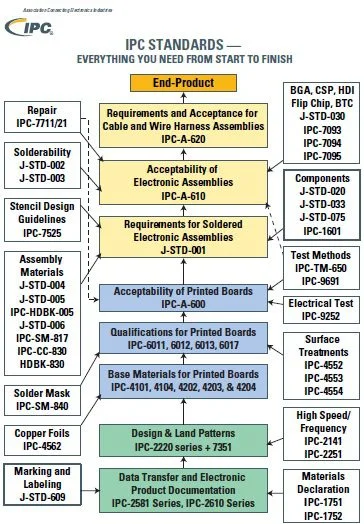
- PCB footprint built to IPC standards with correct land patterns for the target package
- 3D model for mechanical clearance checks and enclosure design
- Accurate parametric data, including operating voltage, temperature range, package type, and lifecycle status
- Datasheet links and reference design pointers so engineers can verify the part before placing it
- Sourcing information tied to distribution channels so procurement can act on the same record the engineer used
When component data follows a standardized structure across every part record, symbols, footprints, and 3D models, engineers spend less time verifying inputs and less time fixing errors that trace back to inconsistent or incomplete library entries. Standardization is what makes the speed gains repeatable and the error reduction predictable across every new design.
Integration Benefits Across the PCB Design Workflow
Connecting manufacturer component data directly to the CAD environment removes several steps that slow engineers down between part selection and schematic placement. The benefits show up at three specific points in the workflow:
- How fast engineers find and place parts
- How accurate the underlying data is
- How updates reach the team without manual intervention
Faster Part Search and Placement
Engineers search for components using parametric filters, part numbers, or functions. An online library that accurately indexes manufacturer data returns results that match what the engineer is looking for, without requiring them to leave their CAD environment. Once found, the part drops directly into the schematic with the correct symbol, and the corresponding footprint is already available for the PCB layout step.
This is where integration saves the most time. A designer who would otherwise spend thirty minutes building a footprint from a datasheet dimension table can place a verified part in under a minute. Across a design with hundreds of unique components, that difference is measurable.
Reduced Design Errors From Accurate Library Data
A significant portion of PCB design errors trace back to incorrect component data: a footprint with wrong pad spacing, a symbol with swapped pins, or a 3D model that does not reflect the actual package height. These errors surface late, often at the fabrication or assembly stage, making them expensive to fix.
Manufacturer-sourced library data reduces this risk because it originates with the people who designed the part. When that data is maintained through a governed online library with version control, engineers always pull from a current, validated record rather than a static file that may not reflect the latest package revision.
Version Control and Library Governance
Version control is the difference between a library that engineers trust and one they work around. When component data is updated, whether due to a package revision, a pin assignment correction, or a lifecycle status change, that update needs to reach the engineers using the part.
An online library with version control handles such an update automatically. The updated record is immediately available across all connected CAD environments, and engineers can view the change history for any part. This removes the manual process of tracking down which version of a footprint is current and distributing updated files across the team.
Supporting Part Selection and Customization
Not every engineer needs the same level of detail during component selection. A hardware architect evaluating a part family needs parametric data and a datasheet link. A PCB designer needs the footprint and 3D model. A procurement engineer needs sourcing data and lifecycle status.
An online library supports all three use cases from the same record. Engineers can also customize symbols and footprints to match internal standards without losing the connection to the manufacturer’s source data. The customized version sits in the team’s local library while the original manufacturer record remains available as a reference.
This flexibility makes adoption easier. Teams do not have to abandon their existing library conventions to benefit from manufacturer-sourced data. They can pull what they need and adapt it to fit their workflow.
Adoption Across EDA Platforms
One practical barrier to component library integration is EDA platform fragmentation. A manufacturer whose parts show up correctly in one tool but not another loses design-in opportunities with engineers using different environments.
An online library that exports to multiple EDA formats solves this. Engineers using Altium, Cadence, KiCad, or any other supported platform pull the same underlying data formatted correctly for their tool. Following library loader best practices during this step reduces import errors and keeps the local library consistent with the source data.
Manufacturers who publish through worldwide distributors and multi-platform online libraries extend their reach without maintaining separate data pipelines for each tool.
Get Started With Ultra Librarian
If you’re looking for CAD models for common components or component library integration for manufacturers, Ultra Librarian helps by compiling all your sourcing and CAD information in one place.
Working with Ultra Librarian sets your team up for success, ensuring streamlined and error-free design, production, and sourcing. Contact UltraLibrarian for partnership opportunities.


 If you’re looking for any of our component footprints or models, we have readily available and free options for you and your design team. Search our library for the solution you’ve been looking for.