One of the most common and yet most required functions in electronic circuitry is conversion. That includes inversion (conversion from DC to AC), rectification (conversion from AC to DC), frequency conversion (AC to AC conversion), and power conversion (which may be AC to AC or DC to DC). However, in the vast majority of cases, regardless of conversion type, transistors are employed.
Metal-oxide-semiconductor field effect transistors (MOSFETs) are often the preferential transistor type for power conversion applications. This is due to their advantages over bipolar junction transistors (BJTs), which include high-frequency operation and other FETs, such as enhancement and depletion mode operation. Infineon is known for producing high-quality MOSFETs, and one that has a long track record of successful implementation is described in the IRFB7545 datasheet.
IRFB7545 MOSFET Benefits and Applications
The IRFB7545 MOSFET is one of many power MOSFETs by Infineon, some of which are developed for deployment in the most hazardous environments like space. The IRFB7545, which can be utilized in many different industries, has the following applications:
IRFB7545 Applications
- DC/DC converter
- AC/DC converter
- AC/AC converter
- Half-bridge rectifier
- Full-bridge rectifier
- Synchronous rectifier
- OR-ing and redundant power switching
- Battery powered circuits
- BLDC motor drive applications
- Brushed motor drive applications
- Resonant mode power supplies
As the list above shows, the IRFB7545 is quite versatile. In addition, the part’s avalanche, gate and dV/dt ruggedness, and RoHS compliance, a feature typical for other Infineon MOSFETs, add to application flexibility.
IRFB7545 Operation and Performance Characteristics
The IRFB7545 excels at typical power MOSFET applications, as well as high-speed and high-power applications. The IRFB7545 datasheet provides important device operational specifications and characteristics to help you fully leverage the component’s features and capabilities.
Important Operational Specifications
Below, the absolute maximum ratings that must be observed for safe operation are listed.
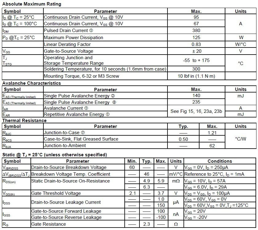
IRFB7545 maximum ratings
In addition to the constraints above, the datasheet also gives electrical specifications, as shown below, to aid your design.
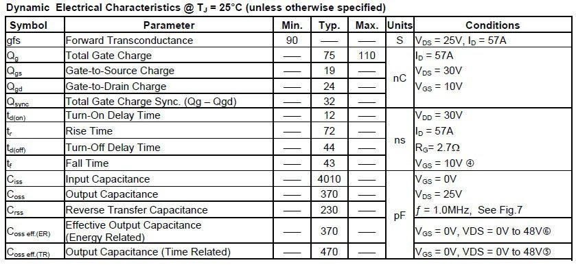
IRFB7545 electrical specifications
Helpful characteristics specific to the device’s diode functionality are given in the table below.
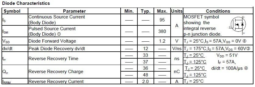
IFRB7545 diode characteristics
The specifications and characteristics above are intended to provide an understanding of the operational limits of the IRFB7545 and give typical values known to yield good results. In addition to these critical parameters, the IRBF7545 datasheet presents several performance testing results, including the ones shown below.
Device Performance Characteristics
Below are a series of characteristics that can compare the IRFB7545’s performance with desired objectives. Included are output curves for various operating conditions and transfer curves extending over the device’s safe temperature range.
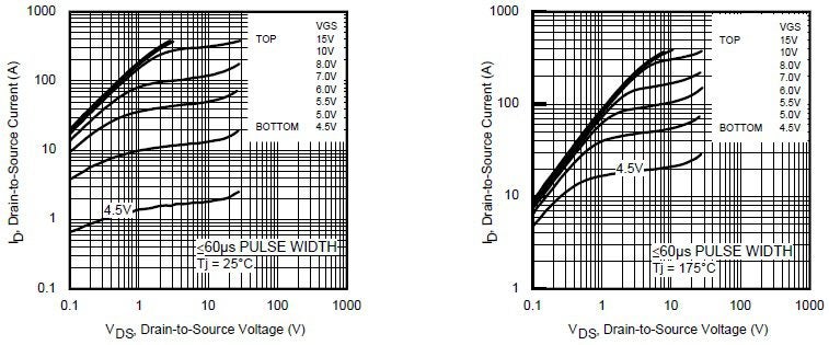
IRFB7545 Output characteristics at 25°C and 175°C
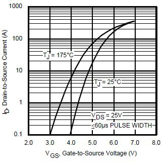
IRFB7545 transfer characteristics
Below, the safe operating area for IRFB7545 is shown.
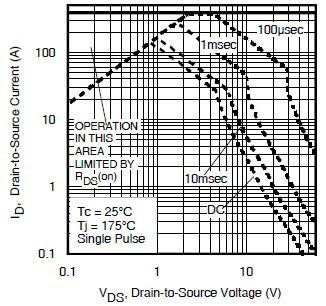
IRFB7545 safe operating area
The figure below illustrates the relationship between Vds and Vgs during switching intervals.
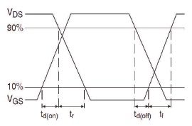
IRFB7545 switching waveforms
The above intervals are controllable by external circuitry and the equations for selecting these passive components are presented in the IRFB7545 datasheet.
Alternative Components
The IRBF7545 is a highly functional and flexible power MOSFET. However, some alternatives may align better with your design requirements. The table below compares two of these alternatives with IRFB7545 for essential design criteria.
The table above lists comparisons between Infineon’s IRFB7545 and alternative MOSFETs IRFB7530 and IRFB7534. For a more comprehensive comparison, please see the datasheets for the IRFB7530 and IRFB7534.
Using the IRFB7545 Datasheet for PCBA Design
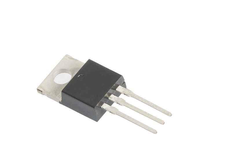
When designing your circuit board with the IRFB7545, you should consult the datasheet for important data and information, as shown below, if you are building your component footprint from scratch.
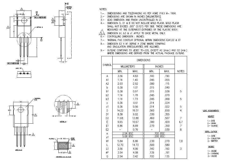
IRFB7545 packaging and mounting dimensions
However, creating accurate component footprints can take time and effort. And errors can lead to redesigns, an excessive turnaround time for your boards, and additional, unnecessary costs.
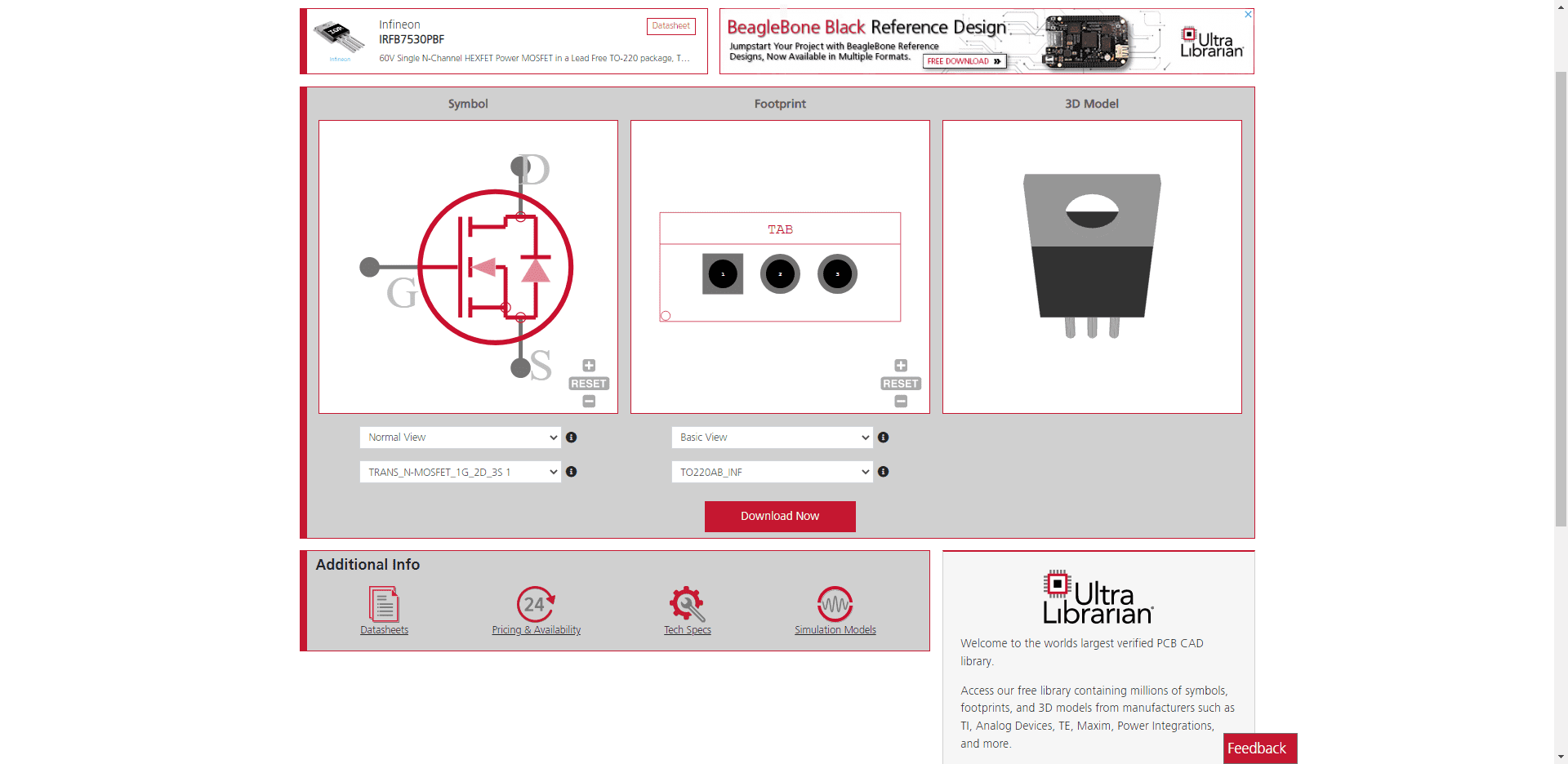
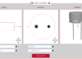
IRFB7530 CAD models from UL
Therefore, the best option is to rely on a trusted industry resource that includes CAD models or equivalents; such as the CAD model above from UL for the IRFS7530 TO-220AB package, which is identical to the IRFB7545 package, that is vetted by the manufacturer, for your electronic parts search.
If you’re looking for CAD models for common components or design data and information like the IRFB7545 datasheet, Ultra Librarian helps by compiling all your sourcing and CAD information in one place. Working with Ultra Librarian sets up your team for success to ensure streamlined and error-free design, production, and sourcing. Register today for free.