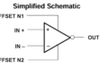
AD584 voltage reference circuit in vector EPS format
The right voltage reference circuit design is crucial for providing a stable and fixed voltage output, regardless of external condition variations such as temperature, power supply voltage, load, humidity, and other variables. The voltage reference generates a constant voltage that can be used as a reliable reference for other components or circuits within an electronic system.
Common parameters associated with voltage reference circuits include:
Voltage Reference Circuit Design
There are several ways to design a voltage reference circuit, each with specific advantages and disadvantages. The three main designs are bandgap voltage reference, shunt voltage reference, and shunt voltage reference.
Bandgap Voltage Reference
A bandgap voltage reference is temperature independent. This device produces a fixed voltage regardless of power supply fluctuations, device circuit load, or, most importantly, operating temperature fluctuations. Bandgap voltage references are popular for applications where better temperature stability and low noise performance are important considerations.
A bandgap voltage reference circuit effectively cancels out the negative temperature dependence of other voltage reference circuits by using a proportional-to-absolute-temperature circuit that is positive temperature-dependent. This provides more consistent and reliable performance than negative temperature-dependent voltage reference circuits.
Shunt Voltage Reference
A shunt voltage reference is a two-terminal model designed to operate within a current range where the reference operates in parallel with its load. It regulates output voltage by adjusting sink current in response to fluctuations in load. A shunt voltage reference exhibits good stability and accuracy over a range of currents and loads in a small PCB footprint.
A shunt voltage reference is often more flexible in non-standard circuit configurations with a lower operating current than a series voltage reference. It effectively imposes no limit on maximum power supply voltage within appropriate power dissipation parameters. With a shunt voltage reference, power supplies deliver the same maximum current regardless of load. As current flows through the load and the reference, the voltage drops to maintain a stable output.
Series Voltage Reference
A series voltage reference has three or more terminals and consumes stable current over a wide power supply voltage range. Load and current are drawn from the input supply only when needed, which is a key advantage. A small amount of current (quiescent) is drawn through internal resistance when not under load. The drop in voltage between input and output is equal to the product of load current times internal resistance, thereby regulating voltage across the circuit.
The series voltage reference is suitable for uses in which the load current or power supply voltage fluctuates significantly over time. The absence of a resistor between the power supply and the reference makes it particularly useful for circuits with high-load currents and minimizes power consumption.
Compared to the shunt voltage reference, the series voltage reference has better initial tolerances and temperature coefficients. Power supply voltage needs to be high enough to enable a voltage drop across the series reference’s internal resistance, but not too high to damage the circuit. The reference circuit’s quiescent current is the only source of power dissipation without load current.
The design details will depend on the application’s requirements, the chosen technology, and the desired level of precision. Additionally, referring to application notes and datasheets from semiconductor manufacturers can provide valuable guidance and insight during the design process.
Voltage Reference Circuit Applications
Voltage references are crucial components in many electronic systems, especially in applications requiring precise voltage levels. Here is a list of the most common applications of a voltage reference circuit:
- Analog-to-digital converter (ADC): ensures accurate conversion of analog signals into digital values.
- Digital-to-analog converter (DAC): ensures the precision of the analog output.
- Voltage regulator: maintains a stable and well-regulated output voltage regardless of changes in input voltage and load conditions.
- Precision amplifier: used to set bias points or establish reference levels for signal conditioning.
- Instrumentation and measurement system: provides accurate and stable voltage levels required for precise measurements.
- Data acquisition system: maintains accuracy when converting analog signals to digital values.
- Voltage and current sensors: plays a role in the calibration and accuracy of voltage and current sensors, ensuring reliable measurements in various applications.
- Precision oscillators: used to set and maintain accurate frequency levels.
- Power management integrated circuit establishes reference voltages for feedback loops, ensuring stable and regulated power supplies.
- Battery-powered device: used with battery management system (BMS) to maintain stable and accurate operation over the entire discharge range of the battery.
- Automotive electronics: ensures accurate and stable operation of engine control units and sensor interfaces in challenging environments.
- Audio processing: used to achieve accurate signal levels and maintain precision in audio processing circuits.
In all these applications, a voltage reference circuit boosts the performance and accuracy of the electronic system by providing a reliable and stable reference voltage, even in the presence of external variations and environmental conditions. The choice of the type of voltage reference and its characteristics depends on the application’s specific requirements.
If you’re looking for CAD models for common components or information on voltage reference circuit design, Ultra Librarian helps by compiling all your sourcing and CAD information in one place.
Working with Ultra Librarian sets up your team for success to ensure streamlined and error-free design, production, and sourcing. Register today for free.


")