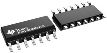
Identifying electronic component problems and solutions requires technical analysis.
There’s a marked difference between designing and manufacturing electronics: the former (solely) does not have to account for many real-world issues when operating as a simulator. Even with a greater mindfulness of design for manufacturing (DFM) practices, the steps between design and manufacturing can vex a strong board design and upend a poor one. For the most part, the bare board fabrication is a relatively straightforward process, provided the manufacturing specs are not overly strenuous. Introducing discrete components during placement and soldering can produce errors during installation or end-user service life. With an understanding of electronic component problems and solutions, designers can incorporate effective analysis practices and avoid common cases of failure.
Diagnosing Electronic Component Problems and Solutions
When analyzing the discrete components of the board, it’s critical to understand the role of different applications and environmental stressors. Engineers rely on manufacturer datasheets for important design information on general operating conditions and maximum ratings for circuit attributes like voltage, current, etc. However, after the application of stressors for a considerable duration or with enough intensity, components can experience failure.
Common indications of failure events are cracked packaging or burnt/scorched substrate. For critical designs–for example, automotive, aerospace, and medical devices–circuit protection and/or isolation techniques are typically employed to limit failure damage. However, component failure can be an issue for virtually all designs, as many root causes can go undetected.
A dedicated part of electronics manufacturing consists of various diagnostic tools that can validate board production and diagnose easier-to-miss failure mechanisms. Consider the overarching avenues of failure and how designers and manufacturers can sidestep (or mitigate) many of these issues, as listed below.
| TYPICAL ELECTRONIC COMPONENT PROBLEMS AND SOLUTIONS | |||
| Problem | Failure mechanism | Diagnosis | Solution |
| Solder joint | Mechanical | Brittle/cracked solder joint that doesn’t exhibit electrical continuity | Assembly rework; consider reviewing the thermal profile of solder processes |
| Electrostatic discharge (ESD) | Electrical | Arcing evidence between neighboring components due to breakdown voltage | Space components further from high-current/voltage networks |
| Coefficient of thermal expansion (CTE) mismatch | Thermal | Most often, cracked solder joints/copper features without evidence of burning | Check materials (substrate, solder, and components) are CTE matches |
| Environmental contamination | Varies | Moisture or debris ingress to the circuit board can provide short/open circuits | Build a rugged enclosure that fully encapsulates the board, except for I/O interfacing |
Navigating Component Manufacturer Supply
Some electronic component problems do not concern PCB manufacturer quality. Instead, designers must consider the various market conditions affecting cost and availability. Like any other good, PCB can experience price shocks due to a decrease in supply or a spike in demand. Thereseveraler of factors at play here:
- Inventory shortfalls – Supply chain issues owing to larger circumstances can create a supply-demand gap. A manufacturer may install limits on orders to distribute the available supply more evenly.
- Obsolescence – Manufacturers will eventually end production, even for popular product lines, to focus on newer and more lucrative components. The announcement of obsolescence can cause a supply run, or design teams may have to pivot to different replacement components.
- Availability—When working toward project deadlines, manufacturer lead times (especially for back-ordered components) also present a significant hurdle.
A procurement team can analyze the production status of all the components in the design and verify that they haven’t entered end-of-life status (i.e., progressed to obsolescence).
Ultra Librarian Leverages Millions of Components
Awareness of common electronic component problems and solutions is critical for devising a successful plan to mitigate manufacturing and operational failures. In addition to applying best practices for board layout design and incorporating your CM’s DFM practices, a winning strategy is the adoption and implementation of a PCB verification checklist that begins with optimizing your CAD library. Fortunately, Ultra Librarian has the solution for design teams looking to broaden their potential pool of suitable components. Best of all, Ultra Librarian is free to register, and users can leverage industry-leading data vendor support to keep layout designs and market analysis competitive.
Working with Ultra Librarian sets up your team for success to ensure streamlined and error-free design, production, and sourcing. Register today for free.


