


The variation in the type of connectors available makes it essential to follow a good PCB connectors guide to optimize your product’s functionality and operation.
Electronic circuit boards rarely operate in a vacuum. Consequently, it is critically important to select the best connector that meets your electrical and mechanical requirements. This is especially important for ECAD-MCAD integrated product designs. By understanding the options and following PCB connectors guide best practices, you can achieve your design’s performance objectives and improve your design and development workflow.
PCB Connectors Guide: Selection Guidelines
The number of different connectors is extremely vast. Nevertheless, choosing the right connector for your design is a required undertaking. For efficiency, it is best to view connectors in broad common types and follow important selection criteria as shown in the table below.
Note: Ratings vary by manufacturer and specific part numbers. Always verify specifications with component datasheets.
For simplicity, connectors are often classified according to where or how they connect to the PCB, such as backplane, wire-to-wire, wire-to-board, or board-to-board. Understanding these distinctions is fundamental to selecting the best connector for your project.
PCB Connectors by Connection Type
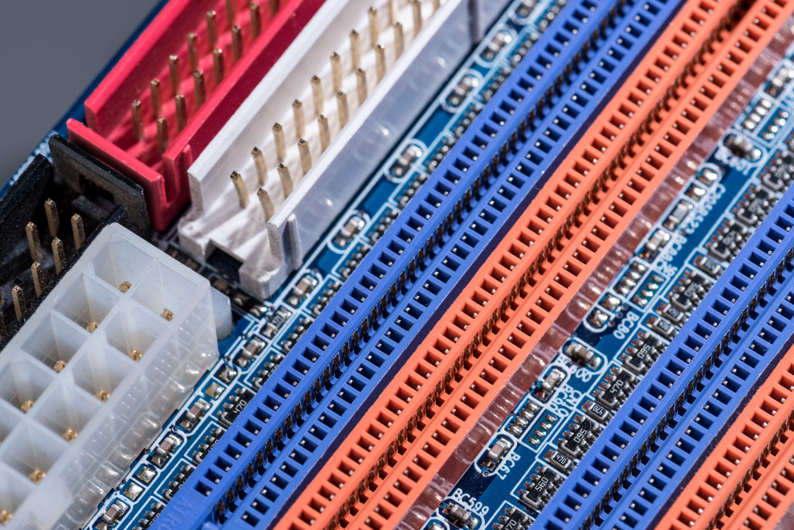
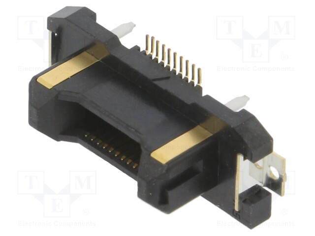
Backplane Connectors
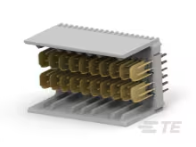

TE Connectivity 6469025-1 backplane connector. CAD models available from UL.
Backplane connectors serve as the backbone of complex electronic systems, providing high-density interconnections between multiple circuit boards. These connectors excel in applications requiring numerous signal paths and robust mechanical connections.
Key characteristics:
- Pin counts ranging from 50 to over 1,000 contacts
- Differential pair routing capabilities for high-speed signals
- Robust mechanical retention systems
- Support for multiple voltage domains on a single connector
Typical applications include:
- Server and networking equipment
- Telecommunications infrastructure
- Industrial control systems
- Military and aerospace electronics
Design considerations: Signal integrity becomes critical with backplane connectors due to their high pin density and long trace lengths. Proper impedance control, crosstalk mitigation, and power delivery planning are essential for reliable operation.
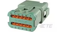
Wire-to-Wire Connectors

.
TE Connectivity prdt04-12pc-be02 wire-to-wire connector. CAD model available from UL.
Wire-to-wire connectors enable flexible cable-to-cable connections, making them indispensable for systems requiring field serviceability or modular assembly. These connectors prioritize ease of connection and disconnection while maintaining electrical reliability.
Key characteristics:
- Field-replaceable connections
- Flexible system routing
- Support for various wire gauges
- Available in sealed and unsealed configurations
Typical applications:
- Automotive wiring harnesses
- Industrial equipment interconnects
- Power distribution systems
- Sensor and actuator connections
Wire-to-Board Connectors
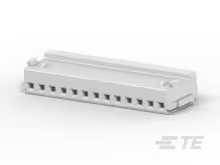
TE Connectivity 1-353908-3 wire-to-board connector. CAD model available from UL.
Wire-to-board connectors bridge the gap between external cables and PCB circuitry, offering the most common interface solution in electronic systems. These connectors balance cost, performance, and assembly convenience.
Key characteristics:
- Cost-effective manufacturing
- Wide variety of termination options
- Excellent availability across suppliers
- Simple assembly processes
Typical applications:
- Terminal blocks for industrial applications
- Header connectors for prototyping and development
- Circular connectors for harsh environments
- Modular connectors for telecommunications
Board-to-Board Connectors

Hirose FX23L-20P-0.5SV8 board-to-board connector. CAD model available from UL.
Board-to-board connectors enable direct PCB-to-PCB connections, maximizing space efficiency in compact electronic designs. These connectors eliminate cable assemblies while providing secure mechanical and electrical connections.
Key characteristics:
- Minimal Z-height profiles available
- High-density contact arrangements
- Integrated alignment features
- Support for flexible and rigid PCB combinations
Typical applications:
- Mezzanine connectors for stacked PCBs
- Edge card connectors for expansion slots
- Micro-pitch connectors for mobile devices
- High-speed connectors for data applications
Common Selection Challenges:
The most important selection challenges to consider for performance are electrical, mechanical, and environmental considerations, as listed below.
Electrical Requirements
Electrical specifications form the foundation of connector selection and directly impact system performance and reliability. Current rating, voltage rating, and contact resistance determine whether a connector can safely handle your application’s power requirements.
Current rating considerations:
- Continuous current vs. pulse current capabilities
- Derating factors for temperature and altitude
- Contact plating effects on current capacity
- Thermal management requirements
Voltage ratings encompass:
- Working voltage under normal conditions
- Withstand voltage for transient protection
- Creepage and clearance distances
- Insulation material properties
Contact resistance impacts:
- Power dissipation and heating
- Signal integrity in high-frequency applications
- Long-term reliability and degradation
- Connection quality monitoring
Mechanical Factors
Mechanical specifications ensure that connectors maintain reliable connections throughout their operational life. Mating force, retention strength, and durability testing provides insight into long-term performance expectations.
Mating force optimization balances:
- Easy assembly and disassembly
- Reliable electrical contact pressure
- Connector and PCB stress limits
- Automated assembly equipment capabilities
Retention mechanisms include:
- Friction-based retention for cost-sensitive applications
- Positive locking systems for high-reliability needs
- Threaded couplings for harsh environments
- Quick-disconnect options for maintenance access
Environmental Considerations
Environmental factors significantly influence connector selection, particularly for applications exposed to temperature extremes, moisture, chemicals, or mechanical stress.
Temperature performance affects:
- Contact material selection and plating
- Insulator material properties and stability
- Thermal expansion and mechanical stress
- Long-term aging and degradation rates
Useful Ingress Protection (IP) levels:
- IP20: Basic finger protection, indoor use
- IP54: Dust protection, splash resistance
- IP67: Dust-tight, temporary immersion protection
- IP68: Dust-tight, continuous submersion capability
Common Design Challenges and Solutions
In addition to selecting a connector for electrical and mechanical durability, it is also important to consider other PCB design challenges at this stage. These considerations include signal integrity, power integrity, component placement and routing, and thermal management.
Signal Integrity Challenges
High-frequency signal transmission through connectors presents unique challenges that require careful design attention. Impedance discontinuities, crosstalk, and signal loss can significantly impact system performance.
Impedance control strategies:
- Controlled impedance connector designs
- Proper PCB trace routing and layer stackup
- Ground plane continuity across connectors
- Differential pair routing techniques
Crosstalk mitigation involves:
- Adequate spacing between signal pairs
- Ground shield placement between critical signals
- Balanced differential signaling where appropriate
- Proper connector pinout assignments
Power Delivery Optimization
Power connectors face unique challenges related to current capacity, voltage drop, and thermal management. Inadequate power delivery design can lead to system instability or component failure.
Current capacity optimization:
- Multiple pins for high-current paths
- Proper contact plating for low resistance
- Thermal management considerations
- Voltage drop calculations across the connection
Power integrity considerations:
- Decoupling capacitor placement near connectors
- Power and ground pin arrangements
- Inrush current management
- Hot-plug capability requirements
Placement and Routing Guidelines
Strategic connector placement significantly impacts PCB layout efficiency, signal integrity, and manufacturing yield. Following established guidelines will help designers avoid common pitfalls.
Placement best practices:
- Position connectors near board edges for accessibility
- Maintain adequate clearance for mating and cable routing
- Consider component height restrictions and mechanical constraints
- Plan for test point access and inspection requirements
Routing optimization:
- Minimize via usage in high-frequency signal paths
- Maintain consistent trace widths for impedance control
- Provide adequate ground plane coverage
- Route power and ground connections with appropriate trace widths
Thermal Management Strategies
Thermal considerations become critical for high-current connectors and dense PCB layouts. Proper thermal management prevents performance degradation and extends connector life.
Heat dissipation techniques:
- Thermal vias near high-current contacts
- Copper pour areas for heat spreading
- Component placement to avoid thermal hot spots
- Airflow considerations in enclosure design
Temperature monitoring options:
- Thermistors near critical connectors
- Thermal imaging during prototype testing
- Derating calculations for elevated temperatures
- Material selection for high-temperature applications
Following PCB connector guide recommendations for selection and design is essential to ensure that your board will not only function as intended internally, but will also contribute to and not detract from the overall system operation and performance.
If you’re looking for CAD models for common components or the best PCB connectors guide for your design, Ultra Librarian helps by compiling all your sourcing and CAD information in one place.
Working with Ultra Librarian sets up your team for success to ensure streamlined and error-free design, production, and sourcing. Register today for free.


