
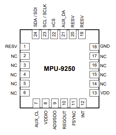
MPU9250 Pin Out Diagram
From the smartphone in your pocket to the latest drone buzzing overhead, motion tracking technology powers countless innovations. That’s where devices like the MPU9250 come in, offering a compact, all-in-one solution for precise motion sensing. They capture acceleration, rotation, and magnetic field data to determine how an object moves and positions itself in space. This tiny marvel integrates a 3-axis gyroscope, a 3-axis accelerometer, and a 3-axis magnetometer, alongside a sophisticated Digital Motion Processor (DMP).
This article provides a comprehensive overview of the MPU9250 datasheet, giving you a clear, specific, and accurate breakdown of its capabilities, electrical characteristics, interfaces, and advanced features. So, let’s see what makes this 9-axis chip tick.
Overall Key Sensor Specifications
MPU9250 Product Overview
The MPU9250 is constructed as a multi-chip module (MCM), meaning it consists of two separate silicon dies fused into one 3x3x1mm QFN package. One die handles the 3-axis gyroscope and the 3-axis accelerometer, while the other houses the AK8963 3-axis magnetometer. This integration means you’re getting nine degrees of freedom (9-axis) motion tracking in a single component.
- The MPU9250 also includes an on-chip Digital Motion Processor (DMP). The DMP excels at handling complex motion processing algorithms, including sensor fusion (combining data from all three sensors to get a complete picture of orientation) and low-power functions such as gesture recognition and pedometry.
- Another benefit of the MPU9250 is that it is also pin-compatible with its predecessor, the MPU6515, which can simplify upgrades for existing designs.
The integration between sensors, combined with on-chip processing and a tiny form factor, makes it a go-to solution for engineers designing a wide array of compact, power-sensitive devices like smart wearables, drones, augmented reality headsets, and precise indoor navigation systems.
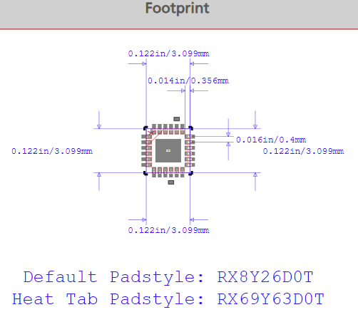
MPU9250 Footprint, taken from Ultra Librarian
Sensor Information from the MPU9250 Datasheet
The MPU9250 doesn’t just combine sensors; it features high-performance versions of each, with the MPU9520 datasheet providing specifications for each.
The Gyroscope: Detecting Angular Velocity
Looking at the MPU9250 datasheet, you’ll see three independent vibratory MEMS (Micro-Electro-Mechanical Systems) rate gyroscopes. These gyros are designed to detect rotation around the X, Y, and Z axes. When the device rotates, the Coriolis Effect causes a vibration within the MEMS structure, which is then detected by a capacitive pickoff. This creates a signal proportional to the angular rate, which is then amplified, demodulated, and filtered on-chip.
These analog signals are then digitized using individual on-chip 16-bit Analog-to-Digital Converters (ADCs). You get a choice when it comes to the full-scale range by setting the full-scale range select (FS_SEL), which can be digitally programmed to ±250, ±500, ±1000, or ±2000 degrees per second (dps).
The gyroscope typically draws about 3.2mA in its normal operating mode. However, when it’s not needed, you can put it into a low-power sleep mode, where it draws only 8µA. The ADC sample rate is also programmable, ranging from an impressive 8,000 samples per second down to 3.9 samples per second, with user-selectable low-pass filters to manage cut-off frequencies.
Selected Gyroscope Specifications
The Magnetometer: Sensing Earth’s Magnetic Field
The 3-axis magnetometer, the AK8963, uses highly sensitive Hall-effect sensor technology to detect magnetic fields. This sensor portion includes magnetic sensors, a driving circuit, a signal amplifier chain, and an arithmetic circuit to process the magnetic field signals. It also sports 16-bit resolution ADCs.
The magnetometer boasts a full-scale measurement range of ±4800 µT (microteslas), with an output data resolution of 0.6µT/LSB (Least Significant Bit). Its normal operating current is about 280µA at an 8Hz repetition rate.
Digital Interfaces
The MPU9250 offers a couple of methods of communication.
Primary I2C and SPI Serial Interfaces
You can choose between an I2C (Inter-Integrated Circuit) or an SPI (Serial Peripheral Interface) serial interface.
- I2C Interface: This is a two-wire interface (SDA for serial data, SCL for serial clock) that’s open-drain and bi-directional. The maximum bus speed for standard I2C communication is 400kHz. The MPU9250 has a 7-bit target address (b110100X) with its LSB (Least Significant Bit) determined by the logic level on pin AD0. This small detail lets you connect two MPU9250 devices to the same I2C bus, provided one has AD0 tied low (b1101000) and the other tied high (b1101001).
- SPI Interface: This is a 4-wire synchronous serial interface using SCLK (Serial Clock), SDI (Serial Data Input), SDO (Serial Data Output), and a CS (Chip Select) line from the controller. The MPU9250 also functions as a target in this setup. The maximum frequency for the SCLK is 1MHz for general register read/write operations. However, for reading sensor and interrupt registers, you can go up to 20MHz. SPI operations are typically completed in 16 or more clock cycles, with data transmitted MSB (Most Significant Bit) first and LSB last.
Auxiliary I2C Serial Interface
Beyond communicating with your main processor, the MPU9250 also includes an auxiliary I2C bus, specifically for talking to other off-chip sensors. This means you can hook up things like an external pressure sensor, and the MPU9250 can manage that data for you.
This auxiliary bus has two operating modes:
- I2C Controller Mode: In this mode, the MPU9250 becomes the controller for the auxiliary I2C bus, directly reading data from external digital sensors without needing the system processor to intervene. For example, it can be configured to perform burst reads from a magnetometer, pulling in X, Y, and Z magnetometer data in 2-byte chunks. It can read up to 24 bytes from as many as four auxiliary sensors, with a fifth sensor capable of single-byte read/write.
- Pass-Through Mode: The MPU9250 essentially connects its primary I2C bus directly to the auxiliary I2C pins (AUX_DA and AUX_CL) via internal analog switches. This is handy for configuring external sensors or keeping the MPU9250 in a low-power state if only the external sensors are being used. The logic level for this auxiliary I2C bus is VDDIO.
Below is a simplified block diagram illustrating the I2C interface solution for the MPU9250, showing how the system processor interacts with the MPU9250 and how the MPU9250 can, in turn, manage auxiliary sensors.
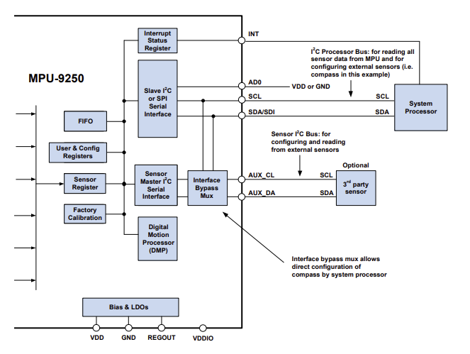
MPU9250 Block Diagram I2C Interface Solution
If you’re looking for CAD models for common components or in-depth technical data like the MPU9250 datasheet, Ultra Librarian helps by compiling all your sourcing and CAD information in one place. You’ll find verified symbols, footprints, and 3D models for the MPU9250 and countless other parts, ready for your ECAD/MCAD integration. All component models can be imported into popular ECAD applications, and you’ll have access to sourcing information from worldwide distributors.
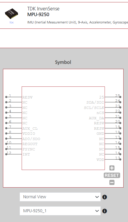
CAD data for the MPU9250 from Ultra Librarian
As shown above, Ultra Librarian provides CAD data for your schematic, PCB layout, and 3D simulations, ensuring smooth ECAD/MCAD integration.
Working with Ultra Librarian sets your team up for success, ensuring streamlined and error-free design, production, and sourcing. Register today for free.


")