In professional audio, accurate gain adjustment is foundational to a high-quality audio solution. Whether mixing a live concert or recording in a studio, engineers need gain controls that feel smooth and sound transparent. Traditionally, this level of control is achieved using analog op-amp topologies with potentiometers, which provide continuous and predictable adjustment.
As digital mixing consoles and remote preamps evolved from these analog designs, gain control became electronically stepped rather than continuous. With this shift, a persistent issue emerged: audible “zipper noise” and pops. These artifacts are caused by sudden, discrete changes in gain rather than the smooth transitions inherent to analog potentiometers. To address this problem, Cirrus Logic has introduced Hybrid Gain Control (HGC) technology in its CS530xP family of Pro Audio Analog-to-Digital Converters (ADCs), which eliminates these artifacts by integrating zero-crossing detection, external analog gain control, and precise digital synchronization into an ADC.
Analog Gain Control Circuit Using Op Amps
At the heart of audio processing lie gain control circuits using op amp topologies. These circuits are designed to provide the best signal-to-noise ratio possible. This is a critical function when recording audio, it lets you capture everything in performances, from the subtle start of an opera to the crescendo of an orchestra. An analog gain control circuit consists of three main elements:
- Low noise discrete BJT: Provides a low noise input
- Op-amp: Used for the control loop, providing the feedback for the BJTs
- Potentiometer: Accurately sets the gain
Although effective, these purely analog implementations are limited by thermal drift, non-linearity, and component tolerances. To achieve the precision required for modern professional audio, engineers evolved the approach by replacing the analog control element with digitally controlled resistor ladders, still adjusting the same op-amp gain stage, but with far tighter accuracy and repeatability. However, these discrete digital steps introduced a new artifact: audible “zipper noise” during gain transitions.
The Challenge of Digital Gain Control
Historically, mic-preamp gain was set with a continuous analog potentiometer. Digital consoles changed this model by placing preamps remotely (often on stage) while controlling them from the desk. This improved cabling and enabled recallable settings, but required a new gain-control method.
Digital preamps typically adjust gain by switching resistor values with analog multiplexers. Unlike a potentiometer’s continuous sweep, these switches introduce discrete gain steps (commonly around 3 dB). To maintain a smooth user experience, system software applies a digital “interpolation gain” after the ADC. As the analog gain jumps up, the digital gain simultaneously steps down, blending the transition into a seamless change.
Why “Zippers” and “Pops” Occur
The complexity lies in synchronization. In a traditional system, the digital gain is handled by a Digital Signal Processor (DSP), often located far from the analog preamp. Misalignment in timing between the analog switch and the digital compensation causes audible glitches.
- Pop: A single, poorly timed gain change creates an instantaneous voltage jump, heard as a click or pop.
- Zipper Noise: Rapidly turning the gain knob creates a stream of these pops, sounding like a zipper being pulled.
Even with analog zero-crossing detection (waiting for the signal to hit 0V before switching), timing latencies between the preamp, anti-aliasing filter, and ADC can essentially guarantee artifacts in discrete designs.
Hybrid Gain Control (HGC) with Cirrus Logic’s CS530xP ADCs
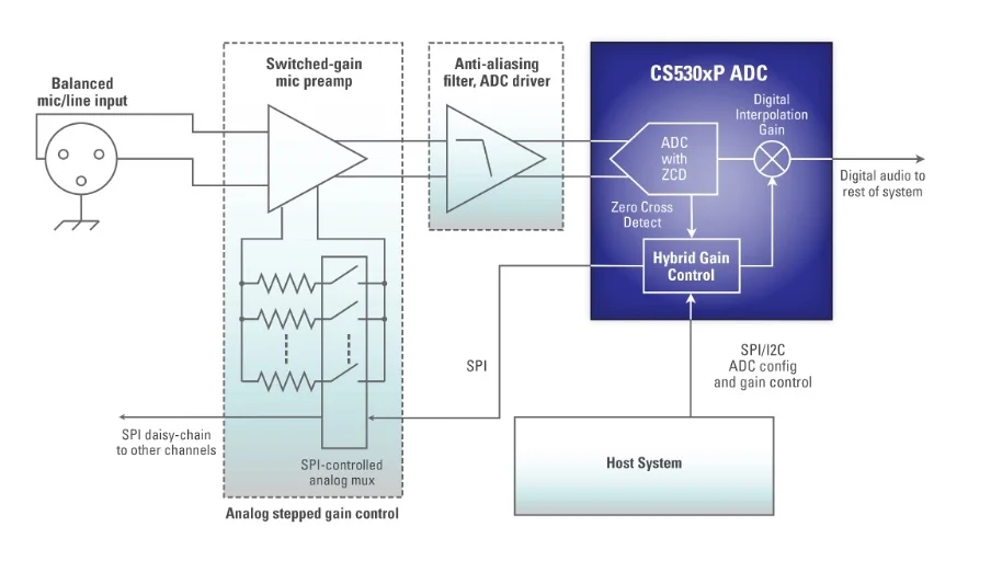
Cirrus Logic’s Hybrid Gain Control (HGC) technology, found in the CS530xP family of Pro Audio ADCs, solves this by integrating the entire control loop into the ADC itself. Instead of relying on a distant DSP, the ADC manages both the analog preamp (via a daisy-chained SPI interface) and the digital interpolation gain internally.
How HGC Eliminates Noise
The HGC architecture coordinates the gain change with microsecond precision:
- Command: The host software requests a new gain setting.
- Analog Prep: HGC sends the new gain bit pattern to the mic preamp via SPI.
- Zero-Cross Detection: The ADC waits for the analog signal to cross zero volts.
- Synchronized Switch: At the exact zero-crossing moment, the SPI Chip Select (CSb) is de-asserted, triggering an instantaneous analog gain change.
- Digital Compensation: HGC waits a configurable duration (typically 4-8 samples) to account for signal path latency, then executes a precise digital gain step to counter the analog change.
- Soft Ramping: Finally, the digital gain smoothly ramps to the target fine-gain value over tens of milliseconds.
This tight integration ensures that the analog step and the digital counter step align perfectly, canceling out the “pop” before it ever reaches the output.
Legacy Control vs. Hybrid Gain Control (HGC)
| Design Criteria | Legacy Digital Gain Control | Cirrus Logic HGC |
| Gain Transition | Discrete steps (e.g., 3dB jumps) executed immediately upon command. | Synchronized analog step + inverse digital step + smooth digital ramp. |
| Audio Artifacts | High risk of “Zipper Noise” (rapid clicks) and “Pops” due to voltage jumps. | Eliminates audible artifacts via Zero-Crossing detection and soft ramping. |
| Synchronization | Difficult; relies on DSP timing, which often drifts from the analog preamp. | Precise; handled internally by the ADC hardware with microsecond accuracy. |
| Hardware Complexity | High; requires external zero-crossing detectors or expensive Multiplying DACs. | Low; control logic is integrated into the ADC and works with standard preamp designs. |
| Auxiliary Control | Requires extra GPIOs or shift registers for Phantom Power/LEDs. | Integrated SPI interface controls up to 64 bits of peripherals (Phantom Power, LEDs, etc.). |
To implement these advanced ADCs in your next professional audio design, accuracy is essential. Ultra Librarian partners with manufacturers like Cirrus Logic to provide verified symbols, footprints, and 3D models. If you’re looking for CAD models for common components or a gain control circuit using op amps, Ultra Librarian helps by compiling all your sourcing and CAD information in one place.
Working with Ultra Librarian sets your team up for success, ensuring streamlined and error-free design, production, and sourcing. Register today for free.