Factory floors expose modern systems to some of the harshest electrical environments. In these spaces, electrostatic discharge (ESD), electrical fast transients (EFT), and high-energy surge events routinely threaten sensitive microcontrollers. Shielding these components takes specialized protection that instantly shunts destructive energy away from signal lines, a job built for Transient Voltage Suppressor (TVS) diodes. This TVS diode selection guide explains the real-world threats defined by the International Electrotechnical Commission (IEC) standards, why TVS diodes are not interchangeable with Zener diodes, and how to correctly choose protection components that keep industrial electronics operating reliably in electrically hostile environments.
Three Transients That Kill Industrial Electronics
Without Transient Voltage Suppressor (TVS) diodes placed at every exposed interface, high-energy events will simply destroy the internal protection structures of microcontrollers and transceivers. Every exposed interface (e.g., connector, power rail, and communication bus) acts as an open door for three primary classes of electrical transients: electrostatic discharge, fast-switching bursts, and massive energy surges.
Electrostatic discharge (ESD) happens when a localized buildup of static charge suddenly finds a path to ground. A technician touching a sensor housing or plugging in a cable often sparks this event. To standardize resilience against these rapid, high-voltage spikes, IEC 61000-4-2 defines four ESD severity levels. These range from ±2 kV to ±8 kV for contact discharge and from ±2 kV to ±15 kV for air discharge. Level 4, the heavy industrial rating, represents the worst-case human-body discharge directly into exposed connectors and I/O pins.
Beyond human-induced static, automated machinery introduces its own brand of electrical noise. Electrical Fast Transients (EFT) consist of rapid bursts of high-frequency pulses. These transients typically happen when arcing contacts occur during the switching of inductive loads. Think of heavy-duty relays or circuit breakers opening and closing on the factory floor. IEC 61000-4-4 defines the EFT waveform by a rise time of 5 ns and a pulse width of 50 ns.
The final and most destructive threat comes from surge events. These events dump massive amounts of electrical energy into a circuit over a longer timeframe. Surge sources include abrupt large-scale load switching, power system faults, and induced transients from indirect lightning strikes. To simulate these massive energy spikes in test labs, engineers use a specialized setup called a combination wave generator. This equipment is tested in accordance with IEC 61000-4-5 to evaluate surge immunity. It sends a 1.2/50 µs voltage impulse into an open circuit while simultaneously delivering an 8/20 µs current impulse into a short circuit.
Why TVS Diodes Are Not Interchangeable with Zener Diodes
Engineers occasionally attempt to substitute Zener diodes for TVS diodes in protection circuits. This is a reliable path to field failures, and understanding why requires looking at the physics.
Substituting Zener diodes for TVS diodes is a guaranteed path to failure because Zener diodes are optimized for continuous low-current voltage regulation. Their junction area is small, suitable for steady-state currents in the 1-40 mA range. When an industrial transient hits, the peak pulse current through that small junction instantly exceeds its thermal limits, melting it in microseconds.
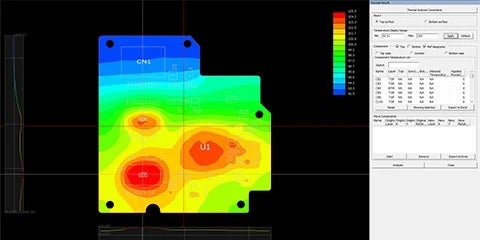
TVS diodes solve this by using a significantly larger p-n junction cross-section, engineered specifically to absorb high-energy transients without thermal damage. Under normal operating conditions, a TVS diode is essentially invisible to the circuit, as it sits in a high-impedance state and draws negligible leakage current. When an overvoltage event occurs, the device enters avalanche breakdown and clamps the transient in the picosecond-to-nanosecond range. The key difference is not just response time, but also peak power handling. A TVS diode rated at 400 W can absorb a transient that would vaporize a Zener in the same footprint.
The practical implication for hardware longevity: never use a Zener for transient suppression unless the datasheet explicitly rates it for pulse power. If the Zener specifies continuous power dissipation, then it is the wrong part.
TVS Diode Selection Guide: Three Parameters That Matter
Picking a TVS diode is not about choosing the highest-voltage rating available. The goal is to tightly bracket signal voltage, keeping the TVS invisible during normal operation while ensuring it clamps before the protected IC is damaged. Three parameters govern such a balance.
Core TVS Parameter Reference
| Parameter | Definition | Selection Criteria |
| Reverse Standoff Voltage (Vrwm) | The maximum working voltage at which the diode stays in a high-impedance state | Must exceed the circuit’s maximum operating voltage to prevent leakage current during normal operation |
| Clamping Voltage (Vc) | Peak voltage across the diode while conducting the maximum rated surge current | Must be below the absolute maximum voltage rating of the protected IC |
| Peak Pulse Current (Ipp) | The maximum surge current the diode can safely shunt before failure | Size for the expected threat; rated using an 8/20 µs test waveform per IEC 61000-4-5 |
A common design mistake is treating breakdown voltage and clamping voltage as equivalent. Breakdown voltage is the voltage at which the device begins to conduct. Clamping voltage is the peak voltage measured across the device while it conducts the full rated Ipp. The clamping voltage is always higher, and that is the number your protection margin must be based on.
The selection logic follows a clear sequence:
- Set Vrwm above the highest expected normal operating voltage on the line
- Confirm Vc is below the IC’s absolute maximum input rating
- Verify Ipp exceeds the peak current expected from the threat environment
- For bidirectional lines, confirm the TVS polarity matches the signal topology
Application-Specific Configurations: RS-485 and IIoT Sensor Lines
Different interfaces require different TVS devices. Applying a generic symmetric TVS to an RS-485 bus, for example, will either clip the common mode range or fail to protect against negative-polarity transients.
Take the SM712 TVS diode, for example. Manufactured by companies like Semtech and Littelfuse, this industry-standard array is designed specifically for asymmetrical (+12V to -7V) protection in multi-point RS-485 data transmission networks. The RS-485 standard specifies a ±7V ground difference between devices on the bus, permitting the bus voltage to range from +12V to -7V. A symmetric TVS would clip the positive common mode range before the bus even reaches its upper operating limit. The SM712 features 400 W (tp = 8/20 µs) of power-handling capability to accommodate the higher transient voltage levels expected in extended common-mode applications.
For Industrial Internet of Things (IIoT) sensor inputs and high-speed data lines, parasitic capacitance becomes the critical limiting factor. A TVS diode’s junction capacitance forms a low-pass filter with the line impedance, degrading signal edge rates at high frequencies. The protection scheme must be matched to the interface speed:
- High-speed data lines (USB, Ethernet): Select low-capacitance TVS arrays, typically under 1 pF, to preserve signal integrity while meeting ESD immunity requirements
- Analog sensor inputs: Moderate capacitance is tolerable, but verify the RC time constant formed with source impedance does not distort measurement bandwidth
- DC power rails: Capacitance is irrelevant here; prioritize high-Ipp unidirectional TVS diodes rated to handle inductive kickback from motors and relays
The capacitance-versus-clamping tradeoff is real. Lower-capacitance devices typically carry higher clamping voltages at a given peak power rating, so confirm the IC’s absolute maximum rating still provides adequate margin before finalizing the selection.
Sourcing and Footprint Accuracy with TME and Ultra Librarian
A verified TVS selection can still fail at the layout stage. Two issues consistently cause problems: counterfeit components and footprint errors introduced during manual library creation.
Global distributors such as TME (Transfer Multisort Elektronik) maintain traceable supply chains directly back to semiconductor manufacturers, ensuring authenticity, full datasheet compliance, and proper storage conditions for moisture-sensitive devices. Procuring from verified channels eliminates the severe risk of counterfeit parts failing silently under transient loads, which ultimately destroys your downstream logic.
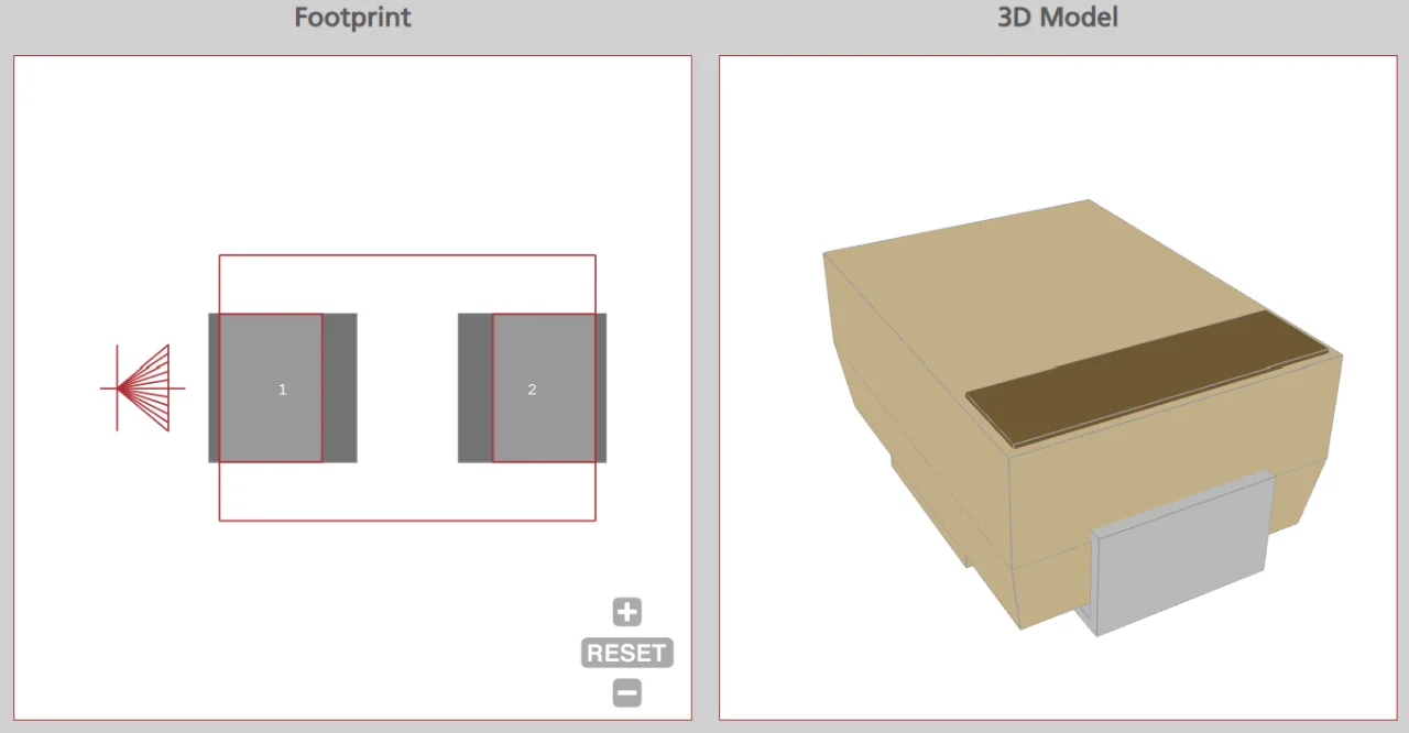
For printed circuit board (PCB) layout, manually building custom SOT-23 or DFN footprints introduces real risks: pad dimension errors, pin assignment swaps, and 3D clearance conflicts that only surface during design rule checks or assembly. Platforms like Ultra Librarian provide manufacturer-verified schematic symbols, PCB footprints, and 3D STEP models ready for immediate import into electronic design automation (EDA) tools. Downloading a verified library part takes minutes; recovering from a pin-swapped protection device on a production board takes weeks.
Following the structured TVS diode selection guide is only half the battle when protecting against harsh industrial transients; ensuring your layout and footprint accuracy is just as critical to avoiding field failures. Ultra Librarian helps you bridge the gap from schematic to final board by providing manufacturer-verified schematic symbols, PCB footprints, and 3D STEP models compatible with all popular ECAD applications. With direct access to real-time availability and pricing from worldwide distributors, such as TME (Transfer Multisort Elektronik), you can design, protect, and procure with total confidence. Register for free today to streamline your protection circuitry layout.
Working with Ultra Librarian sets your team up for success, ensuring streamlined and error-free design, production, and sourcing. Register today for free.



 If you’re looking for any of our component footprints or models, we have readily available and free options for you and your design team. Search our library for the solution you’ve been looking for.