
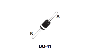
An image of the 1N5819 in a DO-41 package showing the cathode band.
In power electronics design, efficiency is king. Every fraction of a volt dropped across a component can translate into wasted energy, increased heat, and reduced battery life. This is especially true for diodes used in power supply circuits. While standard silicon diodes work well for rectification, their relatively high forward voltage drop can lead to power loss and inefficiency. The 1N5819, a fast-switching Schottky barrier rectifier from STMicroelectronics, is a classic solution to this issue. It is designed specifically for applications where low power loss and high efficiency are critical.
For any engineer designing power circuits, a thorough understanding of the 1n5819 diode datasheet is the first step toward successful implementation. This guide provides an overview of the diode’s key characteristics, common engineering applications, and instructions on accessing its CAD models for your PCB design.
What is a Schottky Diode and Why Use One?
Before diving into the 1N5819, it’s important to understand what makes a Schottky diode unique. Unlike a standard diode, which is formed by joining P-type and N-type semiconductor materials, a Schottky diode is formed by a metal-semiconductor junction.
In other words, current flows primarily using the majority charge carriers (electrons in N-type silicon), without involving the minority carriers (holes) in the same way a PN-junction does. This construction makes it a “majority carrier” device, which gives it two primary advantages and one key trade-off.
- Low Forward Voltage Drop (Vf): A standard silicon diode requires about 0.7V to 1V to turn on. The Schottky barrier is lower, allowing a diode like the 1N5819 to have a forward voltage drop (Vf) as low as 0.4V to 0.5V under load. This significantly reduces wasted power (Power Loss = Vf x If), making it ideal for high-efficiency, low-voltage circuits.
- Fast Switching Speed: Standard diodes have a slow “reverse recovery time” (trr) because they need to clear out stored charge to turn off. As a majority carrier device, a Schottky has almost no stored charge, allowing it to switch from conducting to blocking nearly instantaneously. This makes it essential for high-frequency applications, such as switch-mode power supplies (SMPS).
- Trade-Off: Higher Reverse Leakage (Ir). The metal-semiconductor junction is not as effective at blocking reverse current as a PN-junction. As a result, Schottky diodes inherently have a higher reverse leakage current (Ir) and typically have lower reverse voltage ratings than standard rectifier diodes.
1N5819 Package Information
The most common package for the 1N5819 is the DO-41 axial through-hole package. Its pinout is simple, consisting of just two terminals: the anode and the cathode.
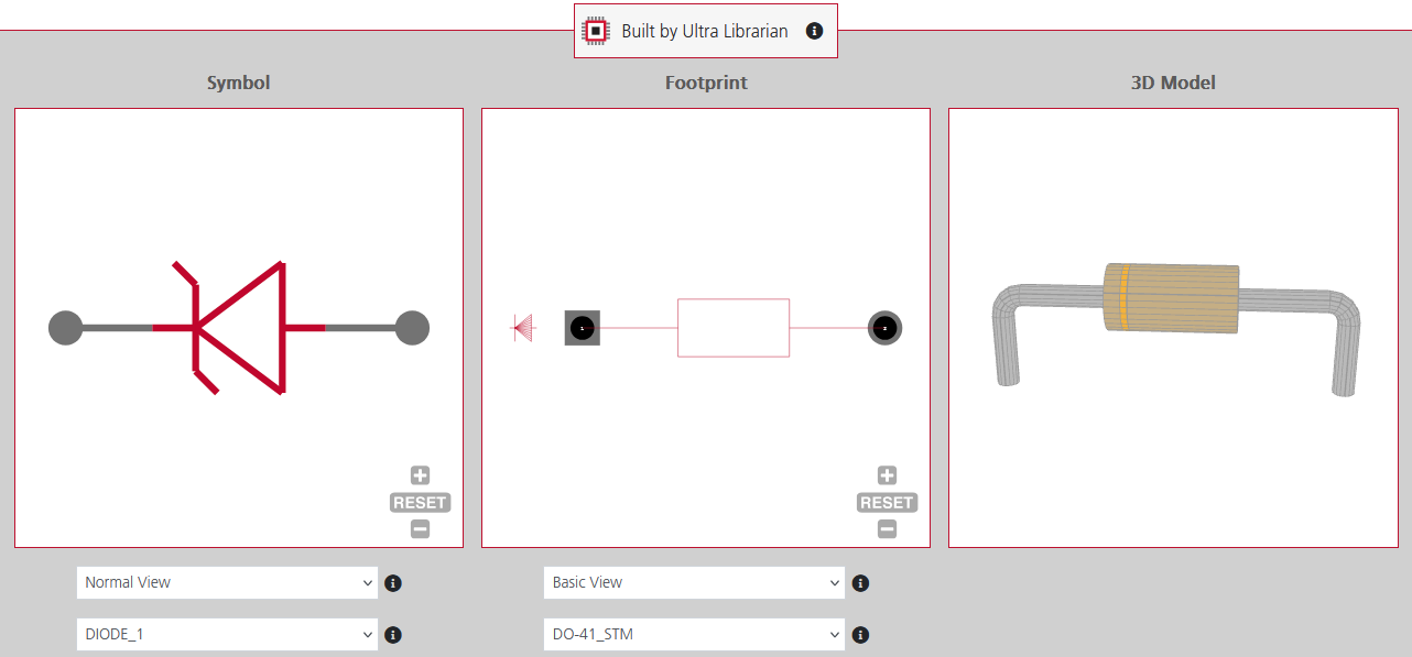
Symbol, footprint, and 3D Model of a1N5819 on Ultra Librarian.
- Anode (A): The terminal where conventional current enters the diode.
- Cathode (K): The terminal where current exits. The cathode is always marked on the physical component by a printed band. It is critical to orient this band correctly on the PCB to ensure the diode is not placed backward.
Common Engineering Uses for the 1N5819
The unique characteristics of the 1N5819 make it highly suitable for several common power electronics applications.


