In the fast-paced world of embedded IoT, Ethernet connectivity is a common requirement for applications that demand reliable wired communication. While the concept is simple, implementing the Ethernet physical layer (PHY), which directly interfaces with the Ethernet cable, requires strict adherence to signal integrity and power management rules. The Microchip KSZ8081 is a premier choice for this task due to its single-supply operation. This KSZ8081 reference guide explores the chip’s subsystems, including power, clocking, and the Ethernet magnetics interface that provides isolation and impedance matching, to help you achieve first-pass design success.
KSZ8081 Reference Design
The KSZ8081 chip is used when a board requires wired Ethernet connectivity using standard twisted-pair cabling, which relies on Ethernet magnetics for signal coupling, isolation, and compliance with standards. The KSZ8081RNA/RND is a highly integrated, single-supply 10BASE-T/100BASE-TX Ethernet PHY for CAT-5 UTP cable. It reduces board cost by integrating termination resistors and a low-noise LDO regulator for its 1.2V core, while offering flexible digital I/O support at 1.8V, 2.5V, or 3.3V.
The device connects to the host processor’s Media Access Control (MAC) via the Reduced Media Independent Interface (RMII). In the block diagram below, we see the complete signal chain: digital data flows from the MAC to the PHY, where it is converted into differential signals (TXP/TXN, RXP/RXN). These signals pass through Ethernet magnetics, transformers, and chokes before reaching the RJ-45 connector. The magnetics provide galvanic isolation, impedance matching, and noise rejection, protecting the PHY and ensuring reliable transmission over CAT-5 cable.
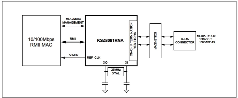
Example System Block Diagram for a KSZ8081RNA chip.
Power Supply and Clocking Strategies
The power delivery network and the clocking architecture are the heartbeat of the system; if either is noisy or unstable, packet loss is inevitable.
Power Supply and Decoupling
The KSZ8081 operates from a single 3.3V supply but generates an internal 1.2V core voltage via an on-chip Low-Dropout (LDO) regulator. To maintain signal integrity, all power supply pins (VDDA, VDDIO, etc.) must be decoupled, which requires a capacitor to be placed between the pin and ground to filter noise and stabilize the voltage. Use high-frequency, low-ESR 0.1µF ceramic capacitors placed as close as physically possible to each pin to provide a low-impedance path. Additionally, use ferrite beads to separate the digital (VDDIO) and analog (VDDA) power domains, blocking high-frequency switching noise.
Power Pin Requirements (KSZ8081RNA)
| Pin Name | Function | Decoupling Requirement |
| VDDA_3.3 | 3.3V Analog Supply | 0.1µF ceramic cap + Ferrite Bead isolation |
| VDDIO | Variable I/O Voltage (1.8/2.5/3.3V) | 0.1µF ceramic cap close to pin |
| VDD_1.2 | 1.2V Core Voltage Output | Do not connect to 3.3V. Requires 1.0µF to 4.7µF cap for LDO stability. |
Clocking and the RMII Interface
In Reduced Media Independent Interface (RMII) mode, the KSZ8081 typically acts as the clock master. In the standard KSZ8081RNA configuration, the PHY uses a 25MHz crystal (±50ppm) to generate and output a 50MHz clock to the MAC via the REF_CLK pin. The MAC must be configured to accept this external clock for synchronized data transfer.
Configuration and Network Interface (MDI) Design
Once the device is powered and clocked, the focus shifts to configuring its behavior and establishing the physical connection to the Ethernet cable.
Configuration Straps (The “Hidden” Inputs)
One of the most common pitfalls in Ethernet design is neglecting the configuration straps. Pins such as PHYAD0, MODE0, MODE1, and CONFIG serve a dual purpose. During the rising edge of the reset signal, the PHY reads the voltage level on these pins to latch its operating mode.
The KSZ8081 reference guide recommends using pull-up or pull-down resistors (typically 4.7kΩ) on these lines. This ensures the PHY boots into the correct state (e.g., Auto-Negotiation Enabled, RMII Mode) regardless of the default internal pull-ups, which can be unreliable in noisy environments.
The Magnetic Interface (MDI)
The connection between the PHY and the RJ-45 connector uses the Media Dependent Interface (MDI), which includes Ethernet magnetics. Ethernet magnetics, typically 1:1 isolation transformers with integrated common-mode chokes, are required between the PHY and the cable. They provide galvanic isolation to protect devices from surges and ground loops, match the 100 Ω differential impedance of twisted-pair cabling, and suppress common-mode noise to improve EMI performance.
- Magnetics Selection: Use a 1:1 turns ratio transformer that includes common-mode chokes on both the transmit and receive sides to suppress noise.
- MDI Termination: The cable-side center taps of the magnetics are terminated with high-voltage capacitors (commonly 2 kV) to shunt common-mode noise to ground, thereby enhancing EMI performance and safety across the isolation barrier.
- Differential Routing: Route the TX+/TX- and RX+/RX- lines as 100Ω differential pairs. Maintain strict length matching (within 50 mils) to prevent phase errors.
KSZ8081 Reference Guide for Board Layout
A schematic represents the logic, but the layout represents the physics. To pass compliance testing, your board must include these layout rules:
- Solid Ground Plane: Ensure that there is a continuous, unbroken ground plane directly beneath the KSZ8081 and the traces connecting to the magnetics. Do not route other signals through this area.
- Isolation: Maintain a distinct separation (typically > 60 mils) between the chassis ground (connector shield) and the digital logic ground. Bridge them only with a high-voltage capacitor and a 1MΩ resistor to prevent floating potentials while blocking DC loops.
- Crystal Placement: Place the 25MHz crystal and its load capacitors as close as possible to the XI/XO pins. Surround the crystal with a ground ring to contain noise.
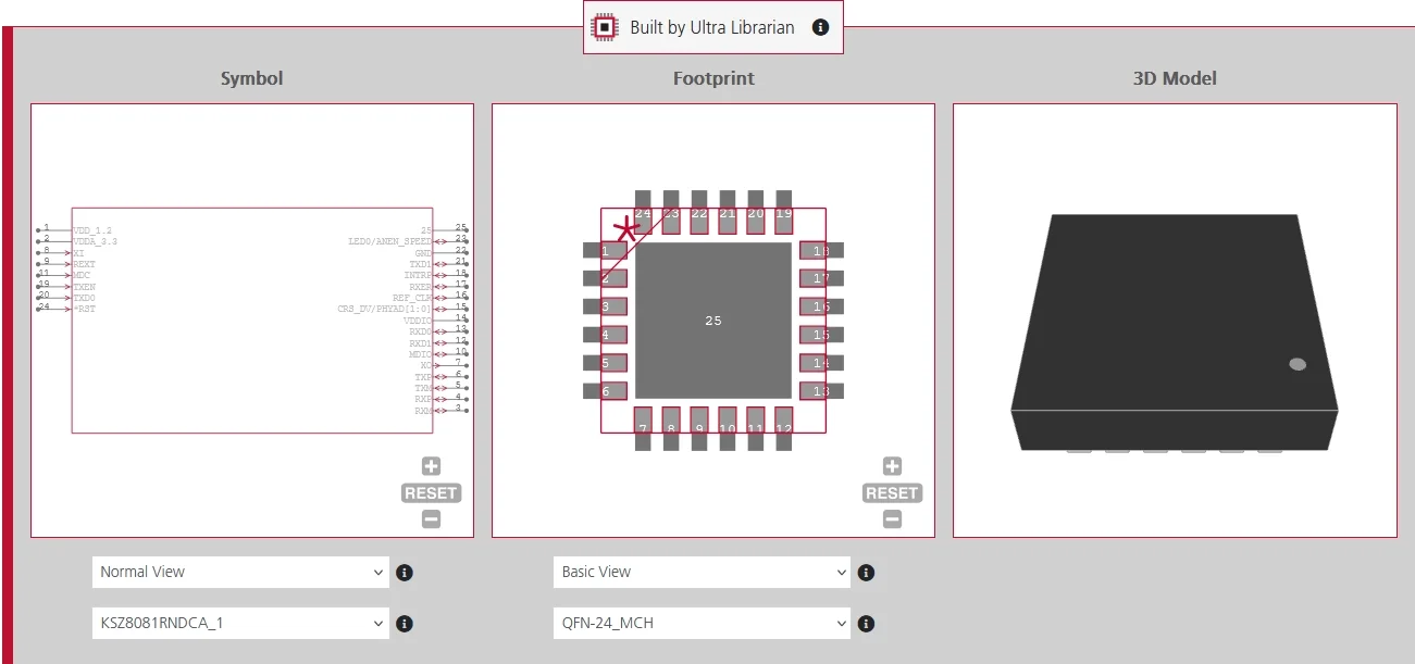
If you’re looking for verified CAD models for the KSZ8081 and its supporting components, Ultra Librarian helps by compiling all your sourcing and CAD information in one place. Our platform provides verified, ready-to-use footprints, symbols, and 3D models that support all popular ECAD applications, along with sourcing information from worldwide distributors.
Working with Ultra Librarian sets your team up for success, ensuring streamlined and error-free design, production, and sourcing. Register today for free.