
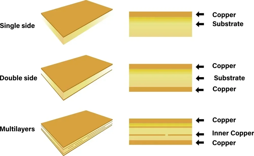
This might be how your PCB is stacked up, but which material should it be made of?
The substrate you choose is just as important as the components you solder onto it. While the majority of printed circuit boards (PCBs) use standard epoxy-based substrates, high-speed and radio-frequency (RF) designs demand something with more fidelity. This brings us to the comparison: FR4 vs Rogers PCB material.
Engineers often default to FR4 because, as the industry standard, it is cheap, available, and sufficiently capable for most digital logic. However, as frequency increases into the gigahertz range, FR4 acts less like an electrical insulator and more like a sponge for signal energy. Rogers Corporation materials, specifically their hydrocarbon ceramic and PTFE (Teflon) laminates, are engineered to handle these stresses.
FR4 vs Rogers: Material Property Comparison
| Property | Metric | Standard FR4 (High-Tg) | Rogers RO4350B | Rogers RO3003 |
| Dielectric Constant (Dk) | ∈r (at 10 GHz) | ~4.2 – 4.5 (Variable) | 3.48 (Stable) | 3.00 (Stable) |
| Dissipation Factor (Df) | Loss Tangent | ~0.020 | 0.0037 | 0.0010 |
| Thermal Conductivity | W/m/K | 0.25 | 0.69 | 0.50 |
| Glass Transition (Tg) | °C | 170 | >280 | N/A (PTFE-based) |
| Moisture Absorption | % | 0.10 – 0.20 | 0.04 | 0.04 |
| CTE (Z-Axis) | ppm/°C | 50 – 70 | 32 | 24 |
Dielectric Constant (Dk) Stability
The Dk of FR4 varies with frequency. It might be 4.5 at 1 MHz, but drops to 4.2 at 1 GHz. This fluctuation makes it difficult to calculate precise impedance traces. If your 50-ohm trace acts like a 45-ohm trace at specific frequencies, you get signal reflections (VSWR issues). Rogers materials maintain a nearly flat Dk across a massive frequency band, ensuring the impedance you simulate is the impedance you get.
Dissipation Factor (Df)
Df is like the “friction” a signal encounters as it moves through the board.
- FR4 (0.020): High friction. At 10 GHz, a significant portion of your signal turns into heat before it reaches the receiver.
- Rogers (~0.003): Low friction. Signal loss is minimized, which is needed for low-noise amplifiers (LNAs) or antenna feeds where every decibel counts.
Thermal Conductivity
FR4 is a thermal insulator (0.25 W/m/K). If you have a high-power RF amplifier, the heat stays localized, potentially damaging components. Rogers RO4350B conducts heat almost three times better (0.69 W/m/K), acting as a localized heat spreader to efficiently transfer thermal energy to vias and heatsinks.
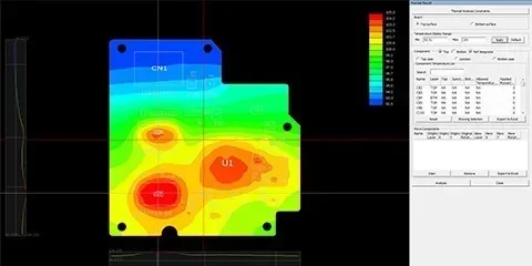
Thermal simulation is important to ensure your components won’t be damaged
FR4 vs Rogers PCB Material Decision Guide
Use this list to determine the right path for your stack-up.
1. Frequency and Bandwidth
- < 1 GHz: Stick with FR4. For standard digital busses (I2C, SPI, UART) and sub-GHz analog signals, the loss characteristics of FR4 are negligible.
- 1 GHz – 10 GHz: Gray Area. You can use high-performance FR4 (like Isola FR408) for short runs, but the Rogers RO4000 series becomes safer for longer traces or matching networks.
- > 10 GHz (mmWave): Rogers Required. At these frequencies, FR4’s dielectric loss degrades signal integrity. You need the physics of PTFE or ceramic laminates.
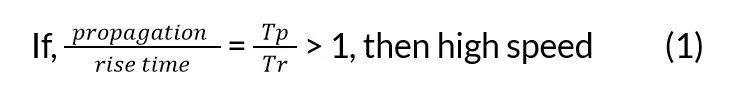
What defines a high-speed signal
2. Signal Integrity Requirements
- Impedance Control: If your tolerance is tight (< 5%), Rogers offers better thickness control and Dk uniformity. FR4 manufacturing tolerances are looser, often resulting in impedance variations of ±10%.
- Phase Sensitivity: For phased array antennas or differential pairs where phase alignment is absolute, the random glass weave texture in FR4 can cause “fiber weave effect” skew. Rogers materials often use uniform ceramic fillers that eliminate this skew.
3. Operating Environment
- High Temperature: Standard FR4 can delaminate or lose structural integrity if repeatedly cycled above its Tg (approx 170°C). Rogers RO4350B has a Tg >280°C, making it stable for high-heat automotive or aerospace environments.
- Outgassing: In space applications (vacuum), standard FR4 outgasses volatiles that can coat optics or sensors. Rogers materials meet NASA low-outgassing requirements.
The Cost Trade-off: Hybrid Stack-ups
The main standout when comparing FR4 vs Rogers PCB material is that Rogers laminates can cost 5 to 10 times more than standard FR4.
If you are building a 12-layer board, making every layer out of Rogers material is exceptionally expensive and mechanically unnecessary. The solution is the Hybrid Stack-up.
You use Rogers material only for the top and bottom layers where the high-speed RF signals route. The inner core layers, carrying power, ground, and low-speed control logic, remain cost-effective FR4.
Pros of Hybrid:
- Cost Efficiency: Reduces total BOM cost compared to a pure Rogers board.
- Mechanical Strength: FR4 is structurally stiffer than some PTFE-based Rogers cores, making the board more durable during assembly.
Cons of Hybrid:
- Fabrication Complexity: The fab house must manage different lamination cycles because FR4 and Rogers cure at different temperatures and pressures. You must verify your manufacturer can handle “mixed dielectrics.”
Real-World Application Examples
To visualize where these materials land, let’s look at two distinct scenarios comparing commodity electronics against high-reliability RF systems.
Scenario A: Standard IoT Gateway
- Tech: Wi-Fi (2.4 GHz), Zigbee, Ethernet.
- Choice: Standard FR4.
- Why: The frequencies here are low enough that the signal loss in FR4 is manageable. The traces are generally short, and cost is the primary driver for consumer IoT devices. Using expensive laminates here would yield no perceptible improvement in performance.
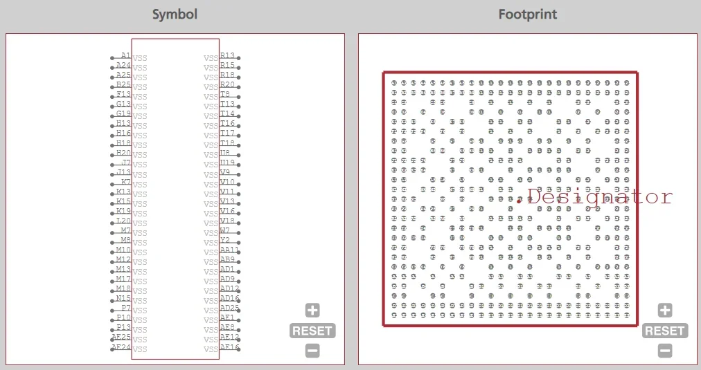
CAD data for TI Internet of Things (IoT) and gateway SoC from Ultra Librarian
Scenario B: Satellite Communication System
- Tech: Ku-band Downlink (12 GHz), Low Noise Block (LNB).
- Choice: Rogers RO4350B.
- Why: In satellite communications, the signal arriving from space is incredibly weak. You cannot afford to lose that signal in the PCB dielectric before it hits the amplifier. RO4350B provides the low dielectric loss (Df 0.0037) necessary to preserve signal-to-noise ratio. Additionally, because RO4350B processes similar to FR4 (unlike pure PTFE), it offers a balance of RF performance and manufacturability for commercial satellite equipment.
When to Use Rogers vs FR4
Selecting the right substrate is usually about balancing physics against economics.
- FR4 is the industry standard. It handles mechanical support, DC power, and digital logic up to a few gigahertz without issues. It is forgiving to manufacture and easy on the budget.
- Rogers is meant for precision. It is necessary when you hit the physical limits of epoxy-glass, specifically regarding dielectric loss, heat, and impedance stability.
Even if you’ve decided between FR4 vs Rogers PCB material, before finalizing your stack-up, make sure to download the specific material dielectrics and layer definitions into your CAD tool. Explore material data, PCB footprints, and component models on Ultra Librarian, compatible with popular ECAD applications and worldwide distributors.
Working with Ultra Librarian sets your team up for success, ensuring streamlined and error-free design, production, and sourcing. Register today for free.


")
")
