

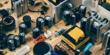
Consumer electronics is one of the most popular BLDC motor applications.
Electric motors consume almost half of the electricity produced worldwide and in industry this figure reached nearly 70% (as of 2017). Brushless Direct Current Motors (BLDC Motors) are increasingly being selected as the motor of choice for drive applications. Specifically, these motors are increasingly being chosen by designers and builders to serve as actuators due to their high reliability, efficiency, and favorable power-to-size ratio.
Fully realizing these benefits depends to a great extent on choosing the right motor type for your application. This requires an understanding of the operation of the motor and driver circuitry. In most cases, BLDC motors are driven by a feedback control circuit composed of a controller and other semiconductor components. Equipped with this knowledge and high-quality components sourced from a reliable resource like TME Electronics, you can create a winning design that maximizes the capabilities of your BLDC motor application.
BLDC Motors: Types and Applications
BLDC motors are classified according to various criteria. For example, inrunner, where the rotor is positioned inside the fixed stator windings, versus outrunner, where the rotor is outside the stator, is one type of differentiation. Winding configuration (single-phase versus three-phase or delta versus wye) is also common for specifying BLDC type. Probably, the most popular is based on the use of Hall sensors for feedback and rotor control, as opposed to using the electromotive force (EMF) from the windings.
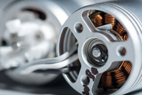
BLDC motor windings
The table above is far from all-inclusive. Instead, it serves to show how pervasive electromechanical devices and, in particular, BLDC motors are in virtually all types of products. As the name suggests, BLDC motors do not use brushes. In their place, permanent magnets are placed in the rotor, and the windings are located in the stator. Currents (of the desired frequency) induce an electromagnetic field and cause the magnets to repel and attract them, setting the axis of the actuator in motion and controlling its speed. Such commutation requires the use of a suitable BLDC motor controller.
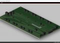
Compact BLDC Motor Controller Design
Electric Motors are ubiquitous in modern appliances and systems. They are in the washing machine, dryer, refrigerator, car, fans, pumps, air conditioners, etc., making our lives easier. Our dependence on these devices makes it important that they work as efficiently as possible. The amount of energy that the actuators consume, to no small degree, is determined by the controller, which controls the operation of the actuator. Below, a compact BLDC motor controller design that meets these qualifications is described.
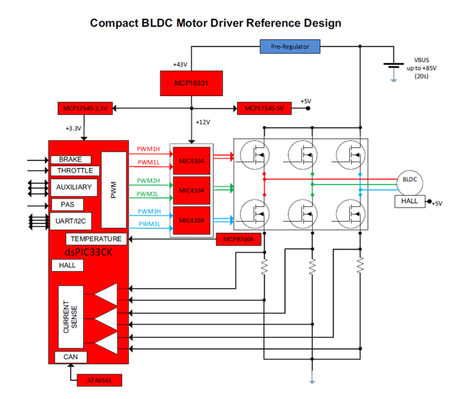
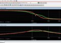
Inrunner sensor feedback BLDC control, which utilizes Hall sensors, is one of the most efficient (approximately 85% – 95%) types of BLDC motor control. As shown above, designing these systems requires making the right component choices for essential functionality, such as monitoring and control, switching and conversion, a well-regulated power supply, and thermal control. Operation and component selections for these functions are described below.
Monitoring and Control:
The heart of the BLDC motor digital control system (DSC, Digital Signal Controller) is the dsPIC33CK256MP505 microcontroller operating at 100MIPS (millions of instructions per second). This chip, in the bottom left corner of the schematic, contains three internal operational amplifiers, which, in this case, measure current. The single-core digital signal controllers of the dsPIC33CK family are built for applications requiring real-time data processing and, therefore, are primarily used in control and protection circuits. In addition, the dsPIC family supports a CAN transceiver that provides native communication with the CAN bus.
These high-performance chips feature extended registers through reduced interrupt latency, a number of integrated peripherals, as well as new instructions to natively support DSP (digital signal processing) operations. The speed of code execution has also been improved, which allows the microcontroller to execute complex control loops in real-time.
These chips are only available in SMD formats: TQFP48 and UQFN48. For prototyping purposes, Microchip has prepared the DM330017 development kits-3. It is important to note that these microcontrollers feature wide thermal tolerance (even from –40°C to 145°C), allowing them to be used in harsh environmental conditions, which are often found in motor control systems.
Power Supply Circuit:
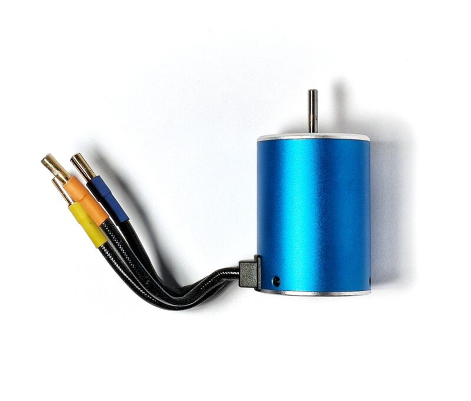
Three-phase BLDC motor
Note that in the circuit presented here, the components operate using three different power supply voltages. For the gate controllers, it is 12V DC; for the microcontroller (DSC controller), 3.3V DC, while the Hall sensor installed in the example motor requires 5V DC. What’s more, in order to broaden the application range of the module and adapt it to typical power supply methods found in different types of electrical devices, it was assumed that the range of acceptable input voltages would be from 12V to 28V. To realize such a power supply circuit, two types of voltage stabilizers were used: MCP16331 and MCP1754.
The MCP16331 chip is an integrated step-up DC/DC converter with high efficiency (up to 96%). Microchip manufactures it in two popular packages, the 6-pin SOT-23, and the 8-pin TDFN. It can operate with input voltages up to 50V and operates at a fixed frequency. The chip is equipped with a number of important functionalities: a high-side switch, peak current control (peak current mode), internal compensation, current limiter, and thermal protection. Only a few external components need to be connected to this integrated power supply, e.g., a resistor divider, which is used to determine the output voltage value. The MCP16331 can deliver up to 500mA by regulating the output voltage in the range from 2V to 24V DC.
The impressive efficiency of the converter is due to the current-limited, high-speed N-type MOSFET transistors with very low resistance. High switching frequency allows the use of small filter elements, which translates into a compact size of the whole system. Integrated Peak Current Mode architecture provides precise output voltage regulation, even during rapid changes on the input line or load side.
EN input (enable) is used to turn the chip on and off. In the off state, it draws only a few microamperes of current, which is beneficial in applications requiring power management, load distribution, and, above all, battery-powered devices. The EN lead is internally pulled to the power line, so the use of this pin is not required (it will be in a steady state, switching on the inverter).
MCP1754/MCP1754S is a family of low dropout (LDO) type voltage regulators (Low Dropout) made with CMOS technology. These chips can deliver current up to 150mA while consuming only 56μA of resting current (typical). They are, therefore, particularly useful in portable applications where low power loss is important. The input voltage range is from 3.6V to 16V DC, making these components ideal for devices powered by 4 to 6 battery cells (e.g., AA or AAA type, etc.), mobile applications with a power supply of approximately 12V DC, and devices powered by one to three Li-Ion cells.
Optimizing Your BLDC Motor Application Design
With small dimensions, low cost, and high performance, the presented design of a compact BLDC motor controller can become the basis for many solutions. Although the circuit can be modified to meet your specific objectives, in this form it will perform excellently in modern applications. Especially for “green” industry, e-mobility, i.e., electric scooters or bicycles.
BLDC motor-driven E-scooters in a harsh environment
Additionally, it is well-suited to power BLDC motors used in high-powered drones and unmanned aerial vehicles (UAVs). Realizing these benefits is assured by following best practices for component library management, schematic design, and PCB layout.
All Microchip components required for the circuit are available from the TME catalog and shipped directly from our warehouses.
If you’re looking for CAD models for common components or essential design information for BLDC motor applications, Ultra Librarian helps by compiling all your sourcing and CAD information in one place.
Working with Ultra Librarian sets up your team for success to ensure streamlined and error-free design, production, and sourcing. Register today for free.

