PCB Standards:
An Engineer's Guide

Designing circuit boards can be a very complex undertaking. The basic paradigm of selecting your parts, drawing the schematic, creating the PCB layout, and verifying your design is challenging in itself. Yet, every design must also adhere to rules and regulations. Failing to do so can make your board unbuildable, unmarketable, and unsafe. 

It is important to follow good guidelines and implement best design practices to avoid these negative contingencies. However, knowing what PCB standards are helpful and which are mandatory is critical.

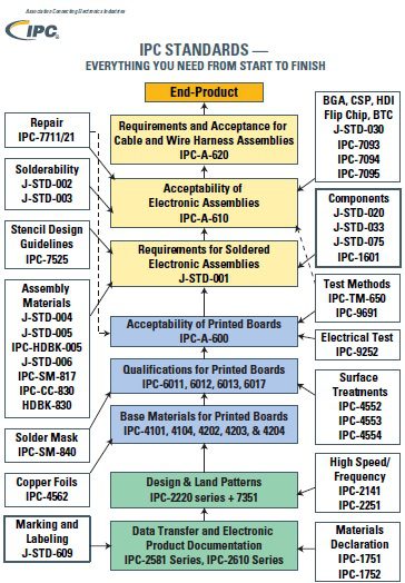
Passing your board’s PCB standards checklist

PCB Standards Engineers Need to Know

There are several organizations that create documents that are intended to ensure the level of performance, quality, and safety of electronic circuit boards.  These include the International Standards Organization (ISO), Electronic Components Industries Association (ECIA), ASTM, International Electrotechnical Commission (IEC), SAE, and IPC, which is the PCB industry leader in developing standards that cover all aspects of board design, manufacturing, and testing. 

The implementation of circuit boards and electronics has expanded into virtually all industries and can be found in the majority of products we rely upon every day. Consequently, PCB standards have increased markedly over the last few decades. Many of these standards target specific or niche components, materials, and/or processes and are only pertinent to designers and engineers for specific designs. As listed in the table below, others are generic and applicable to all PCBA development. 

PCB StandardDescription
IPC 2221This is the most important for designers to be familiar with as it establishes the requirements for all aspects of PCB design and should form the foundation for best practices.
PCB designers and engineers must understand the specifics within which their design choices and specifications must fall. This standard provides these and recommendations and suggestions to help achieve these requirements.
IPC-A-610

This standard defines the acceptability criteria for printed circuit boards. There are three performance classes of acceptance.

Class 1: Lowest acceptance level typically applies to commercial products that do not require extensive board operational lifecycles.

Class 2: Most boards fall in this category where performance should be uninterrupted, although, not mandatory.

Class 3: This classification is for critical use boards where failure could be catastrophic. Products where these boards are used include invasive medical devices–like pacemakers–and aerospace systems.

Knowledge of these classes and performance criteria enable the designer to accurately direct the CM in building their board to a level that meets their objectives and end-user expectations.
J-STD-001This standard provides specifications for soldered electronic assemblies and guidance on how manufacturers can achieve the necessary results. Clearance, spacing, cleaning, materials, equipment, and other topics are covered.
Familiarity with this standard helps board designers choose specifications to aid the CM in ensuring good solder joints and avoiding rework or unusable boards.
The PCB standards listed above are essential for circuit board designers and engineers to know and implement. As lack of awareness does not release you from having to adhere to them. Thus, it is incumbent upon you to understand specifications that impact your design to avoid redesigns, respins, wasted time, and unnecessary development costs.

Standards PCB Designers Should Know

In addition to the standards listed above, it is likely that your specific custom design will require adherence to other standards. For example, depending on whether your design is for a rigid, flex, or rigid-flex board, you should be familiar with IPC 6011, IPC 6012, and/or IPC 6013, which include specifications for the manufacture of generic, rigid, and flex PCBs, respectively. Other PCBA development standards organized according to their application to design (green), fabrication (blue), or assembly (yellow) are shown below.

IPC PCB standards designers should know

IPC PCB standards flowchart

As illustrated above, additional IPC PCB standards provide more in-depth guidance for all of the PCB development stages.

Designing for Standards Compliance

Designing circuit boards is at once open to creativity and constraint. Complying with the established boundaries is critical to ensure your design’s manufacturability and the assembled PCB’s safety and reliability. It is helpful to use guidelines, as listed below, to help you optimize your PCB standards compliance design process.

PCB Standards Compliance Design Guidelines

  • Know and adhere to the PCB standards that must be followed.
  • Be aware of utilizing standards that apply to your specific custom design.
  • Be aware of use standards that can help improve the efficiency of your development process.

Structuring your design process not only to follow but leverage the benefits of PCB standards will result in more efficient development, higher quality boards, and higher yield rates.

If you’re looking for CAD models for common components or important design information like how to ensure compliance with important PCB standards, Ultra Librarian helps by compiling all your sourcing and CAD information in one place. 

Working with Ultra Librarian sets up your team for success to ensure streamlined and error-free design, production, and sourcing. Register today for free.