
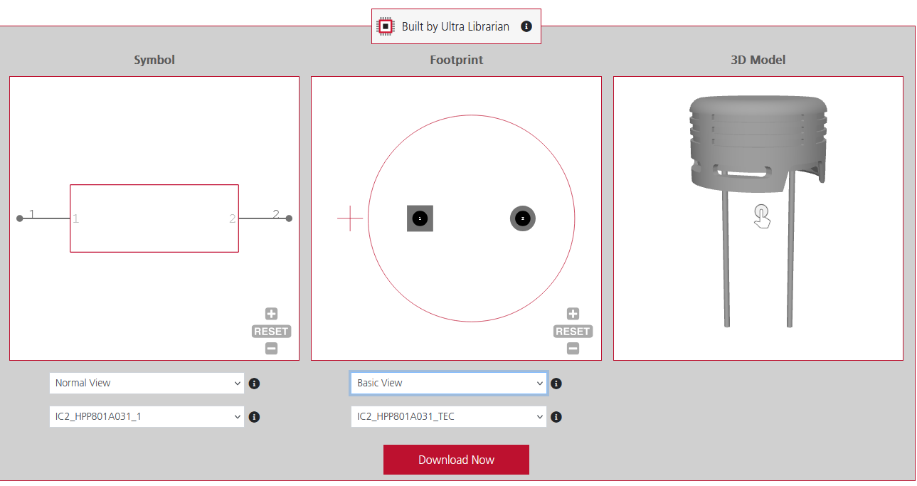
Ultra Librarian provides all ECAD and MCAD data in a single package
Modern electronic systems demand tight integration between electrical (ECAD) and mechanical (MCAD) environments, where mechanical constraints directly influence electrical performance and vice versa. As product geometries shrink and tolerances tighten, the traditional disconnect between electrical and mechanical workflows leads to misaligned models, enclosure interference, and avoidable design re-spins. Effective ECAD and MCAD collaboration depends on a shared source of truth where accurate, metadata-rich component library models ensure both domains are working with consistent geometry, placement, and mechanical definitions.
The Root Cause of the Disconnect
Why does the collaboration between electrical and mechanical CAD often fail? Frequently, it comes down to the data source.
In a disjointed workflow, an electrical engineer might source a schematic symbol from one library and a generic footprint from another. Meanwhile, the mechanical engineer downloads a STEP model from a third-party website that looks “close enough” to the intended part.
This mismatch creates critical risk: the schematic symbol may be correct, but if the 3D model’s solder pads don’t align with the PCB footprint or the component height is inaccurate, the board will not fit the enclosure. Simple block models no longer meet modern design requirements. Effective ECAD–MCAD collaboration depends on three synchronized data assets functioning as one; if any of them is inaccurate or independently sourced, the overall design integrity is compromised.
Managing ECAD and MCAD Collaboration
Successful ECAD–MCAD collaboration requires a mutual understanding of the constraints and objectives inherent to each discipline. It is not enough to simply exchange files; engineers must understand why a component is placed in a specific location to negotiate trade-offs effectively.
What MCAD Teams Should Know
- Physics Dictates Placement: Signal Integrity (SI) often requires specific components (like memory chips and processors) to be grouped tightly to prevent timing failures.
- Invisible Walls: Keep-out zones are required for EMI shielding or high-voltage isolation. A metal enclosure part cannot encroach on these areas even if it physically fits.
- Thermal Needs: Components generate heat. MCAD needs accurate data to design appropriate airflow or conduction paths (like thermal pads to the case) to ensure the device doesn’t overheat.
What ECAD Teams Should Know
- The Z-Axis Landscape: It isn’t just about max height. ECAD must navigate enclosure variances like internal ribs, screw bosses, and heat sinks that restrict height in specific zones.
- Fixed I/O: Connector placement is usually locked by industrial design and user experience constraints. These are fixed anchors that the layout must route around.
- Vibration & Stress: Large, heavy components (like inductors) must be placed near mounting holes or structural supports to prevent solder fracturing during vibration testing.
The Optimized Workflow
Modern workflows replace static file exchanges with incremental data updates. Typically, MCAD defines the board outline and mounting points. ECAD imports this baseline for component placement. Both teams then perform iterative interference checks to catch collisions between tall components and casing features before freezing the design for manufacturing. Common pitfalls include:
- Origin Mismatch: If the ECAD (0,0) point differs from the MCAD assembly origin, imports result in “floating boards” requiring risky manual realignment.
- Tolerance Errors: Designing with “nominal” dimensions rather than “maximum” material conditions leads to assembly failures when physical parts are at the upper limit of their tolerance.
- Loss of Information: Converting native files to generic STEP formats strips critical metadata (net names, power ratings), hindering accurate simulation in the mechanical domain.
ECAD and MCAD Collaboration with Ultra Librarian
The most effective way to bridge the gap between engineering teams is to ensure they are working from a single source of truth. Ultra Librarian supports ECAD and MCAD collaboration by providing verified, unified CAD models that eliminate data discrepancies.
- Unified Model Creation: Unlike scattered free sources, Ultra Librarian builds the symbol, footprint, and 3D model simultaneously using the same manufacturer’s datasheet. This ensures that the logical pin mapping matches the physical pads and that the 3D body aligns perfectly with the footprint.
- Native Format Downloads: Data translation errors are a major source of frustration in collaboration. Ultra Librarian offers downloads in native formats for all major ECAD and MCAD tools (including Cadence, Altium, SolidWorks, and more), ensuring the data behaves exactly as expected in your specific software environment.
- Pre-Verified Accuracy: By using models that are pre-verified and built to IPC standards, teams can bypass the manual “cleanup” phase. Electrical engineers can place parts with confidence, and mechanical engineers can trust that interference checks in their 3D assemblies reflect reality.
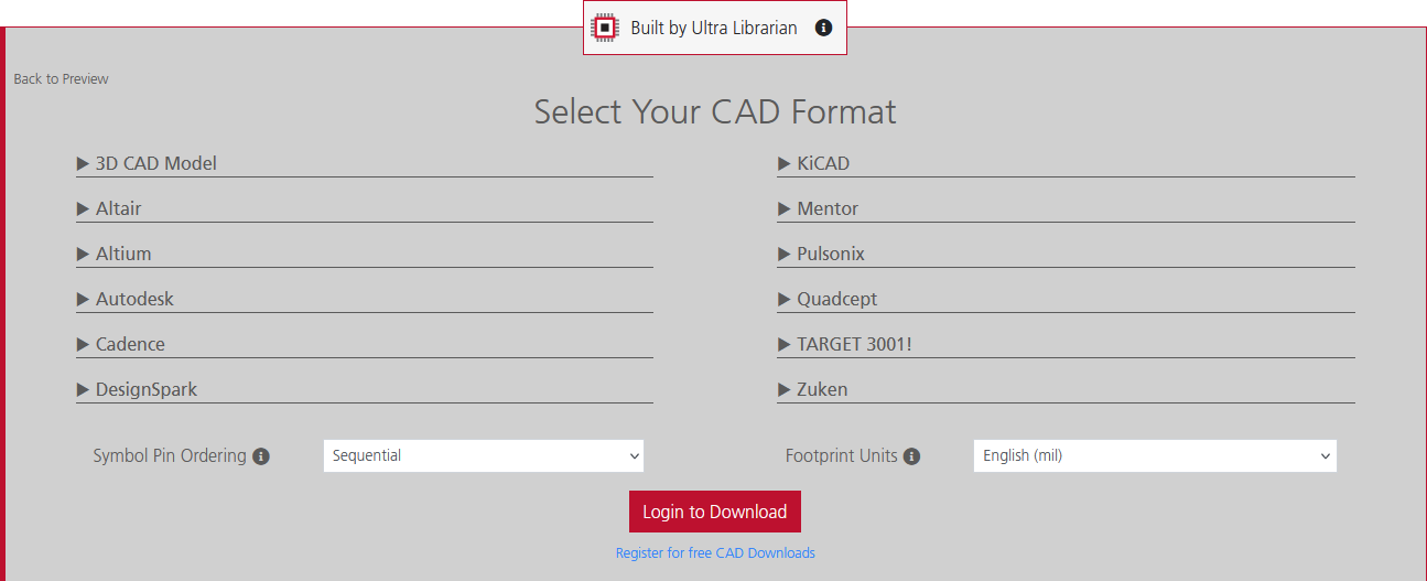
Ultra Librarian enables seamless ECAD and MCAD collaboration by providing CAD data in the native format of your design software.
ECAD and MCAD collaboration doesn’t happen by accident; it happens when both teams trust their data. By adopting a workflow that prioritizes high-quality, unified library data, you eliminate the friction between departments.
If you’re looking for a unified data source for ECAD and MCAD collaboration, Ultra Librarian helps by compiling all your sourcing and CAD information in one place. Explore our extensive library for popular ECAD applications and easily find components from worldwide distributors.
Working with Ultra Librarian sets your team up for success, ensuring streamlined and error-free design, production, and sourcing. Register today for free.


")


