
Some electronics projects require tight control over instructions within and between components. To accomplish this, logical operations are sometimes necessary inside simple components, rather than complex components like computer chips. A logic gate is an example of this. It takes information from multiple inputs into account to determine what type of response it should generate. Depending on the component, a logic gate can control current or simple signals. The SN74LS32N contains a subtype of logic gate called an OR gate. This means the gate produces a certain output when any one of its inputs meets acceptable criteria. As we discuss the SN74LS32N’s capabilities and applications, the SN74LS32N’s datasheet will be an important reference for details about the precise way this logic is implemented.
The SN74LS32N
According to its datasheet, the SN74LS32N contains four separate OR gates, each of which has two separate inputs. A high level of current only flows through a gate if that gate’s two inputs are both conducting high levels of current themselves. Any other scenario results in a low level of current flowing through the gate. The SN74LS32N manages each of its gates independently, and the amount of current flowing through one gate does not affect the output of another.
The SN74* line of logic gates is closely related to another line with similar functionality, the SN54* line. The SN74LS32N is a general-purpose component, as are the other components in the SN74* line. The SN54* line is specifically built for military applications, but thanks to its wider temperature and voltage tolerances, it can also be used for aerospace applications. The datasheet doesn’t go into the specifics of SN54* line uses in military or aerospace industries, but that is because every OR logic gate functions so similarly.
A logic OR gate like the SN74LS32N is useful in detecting sudden changes in input and to respond to them quickly. Therefore, OR gates like the SN74LS32N are common in alarm systems. They are also useful in any scenario where an open or closed state must be monitored, such as seals between compartments or components. Although a single logic gate on the SN74LS32N is not useful for differentiating between more than two states, providing inputs to multiple gates on the component may allow engineers to differentiate between multiple states.
SN74LS32N Logic
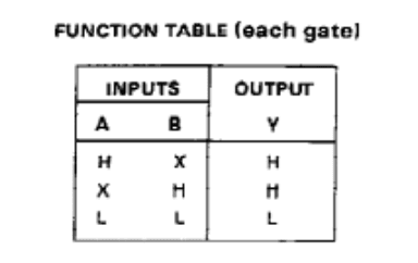
Formally, the SN74* and SN54* lines are positive OR logic gates. This is a roundabout way of saying high levels of output are always expected from the gate unless all inputs are low level. The opposite of this, negative logic AND gates, mandates all levels of output expected from the gate are low unless all inputs are high level. In the function table below, as long as one of the inputs to an SN74LS32N has a high amount of current, the gate will produce a high current output. The X’s in the table show the current level in a particular input doesn’t matter because the requirement for high current output has been satisfied by the other input.
Considerations when Using the SN74LS32N
While there are some significant differences between the SN74* series and the SN54* series, there are also some similarities designers should be cautious of. For example, despite all components in the series having 4 independent logic gates and potentially handling a lot of current, each component only has one ground. The SN74LS32N does not have a built-in heat sink. Similarly constructed components with multiple input groups usually have a ground for each group, as well as a heat sink, to prevent excess current and other problems. A single ground might not handle unexpected high current as well as a component containing multiple grounds.
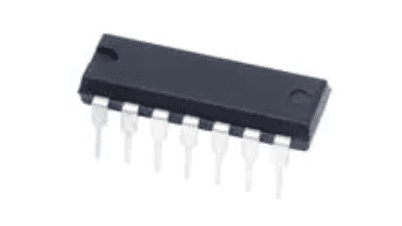
When using the SN54* series, designers should be careful to choose components with the proper shape and configuration for their needs. Most of the components in the SN54* line are shaped and oriented similarly to the SN74* line, with two logic gates on each side of a rectangular component and a single ground on one side. A few components in the SN54* line are significantly smaller and oriented differently in a square shape. The square orientation puts the logic gates in an unusual alignment, allowing inputs and outputs to span multiple sides and leaving multiple pins unused. In addition, the square orientation still has only one ground, even though there is potentially room for more than one. The square components in the SN54* series can prove invaluable when saving space is a major consideration, but their odd configuration makes them more difficult to place properly.
Ultra Librarian provides multiple variants of the SN74LS32N logic gate to give designers precise control over signals within their electronics projects. Working with Ultra Librarian takes the guesswork out of preparing your next great device, and puts your ideas on the road to success. Register today for free.


")


