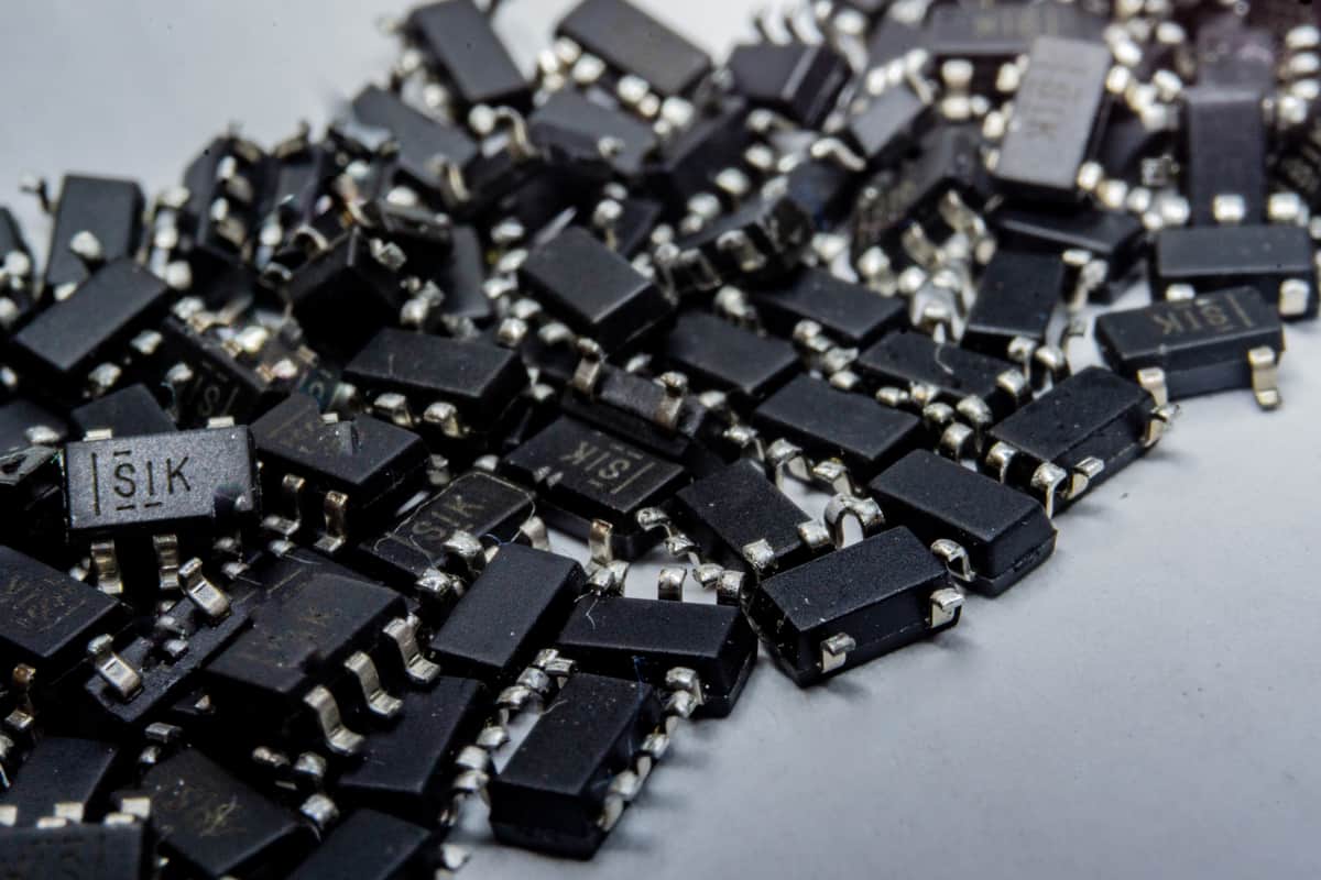
These SOT package types are very similar, but they need different footprints and land patterns for use in CAD tools
You can never tell exactly what function a component provides just by looking at its package. This is true for DIP components, QFN components, and small outline transistor (SOT) package types. In particular, SOT packages are commonly used for a variety of components, ranging from discrete transistors to linear regulators. These components are simple to understand and layout, and they have less chance of defects during wave soldering, as they have larger land patterns than other surface-mount components.
If you’re debating on what package type to use for discrete transistors and other small SMD devices, SOT packages are a common option. It helps to understand the various SOT package types, as not all SOT components are created equal. Once you do select your SOT components, you’ll need to make sure you have the right PCB footprints for your components to use in your CAD software.
SOT Package Types
Different components that come in SOT packages can have different pin counts, lead sizes, lead pitches, and required land patterns. In the case of SMD components, the land pattern gives the required pad size for soldering to the board, which needs to be included in a component library for PCB design. If you know a bit about the different package types, you can figure out how to design the land pattern to accommodate the component on your board. You can also quickly compare different land patterns for SOT package types simply by looking at the package name.
Naming Conventions
The naming convention for SOT packages (and all other SMD packages) is defined in the IPC-7351B: Generic Requirements for Surface Mount Design and Land Pattern Standard. This standard only specifies the land pattern, which then corresponds back to the package outline for the specific SOT package of interest. The SOT package naming convention is shown below, using an SOT223-4 package as an example.
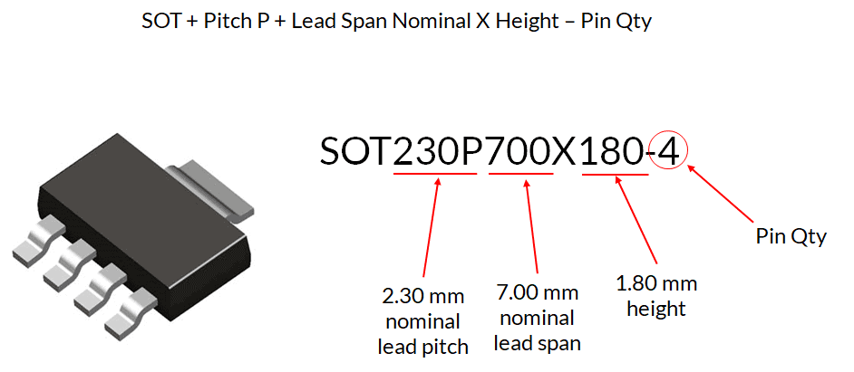
SOT223-4 package drawing and land pattern naming convention
If you examine the standard SOT package types, you’ll see that they have some of the following common characteristics:
- Lead count: The total number of leads ranges from 3 to 8, and in some cases, such as power MOSFETs, the package includes a die-attached paddle.
- Standardized dimensions: All SOT packages have at least one of their dimensions standardized. Not all dimensions are standard, however, and instead are specified as maximum values.
- Low profile: The thickest SOT packages will have a maximum thickness of 1.8 mm. For some SOT package types, this is a maximum (SOT223-4), while other packages have this value listed as the required nominal thickness (SOT223-5).
- Gull-wing leads: The lead style on SOT packages is a gull-wing lead, which allows easy soldering to a PCB. These components are generally large enough that they can be soldered with a fine-tip soldering iron by hand if necessary.
Selecting Components in SOT Packages
Understanding the land pattern also aids component selection. Deciding between through-hole vs. surface-mount assembly, or between different SMD package types, is sometimes simply a choice between different pad sizes and required clearances. From the above example, we can quickly identify the lead pitch, which can then be matched to a trace thickness that may be required for power electronics applications.
The lead count can also be instantly seen from the package name; for example, all SOT89-5 components come in an SOT89 package with 5 leads. Be sure to check the component datasheet of an SOT package footprint guide to see if your component includes a die-attached paddle. In the case of our example SOT89-5 component, two of the leads on the package outline are actually bridged as a single lead (see below).
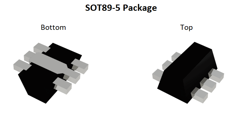
SOT89-5 package drawing. Notice that the central leads on the bottom of the component body are bridged.
Common Components in SOT Packages
Because SOT packages only have up to 8 pins, they are not used for complex integrated circuits. However, these packages are still used for a range of common components. Some examples are:
- Discrete power transistors (typically supporting a few dozen volts of breakdown voltage and several amps of on-state current)
- Power regulators (such as the TPS79915DDCTG4 LDO from Texas Instruments)
- Analog amplifiers (operational, instrumentation, and transimpedance amplifiers)
- Schottky diodes and rectifiers for AC-DC power conversion
- Window detectors, comparators, or other analog components
- Optoisolators and phototransistors
No matter which type of component you want to use in an SOT package, you need to ensure your CAD data contains the correct footprint information, particularly the land pattern, designator, and courtyard outline. The easiest way to get this information is to use an electronic parts search engine that also supplies CAD models for components.
Find the SOT Components You Need with an Electronic Parts Search Engine
Instead of creating PCB footprints, schematic symbols, and 3D drawings by hand, you can save yourself time and headache by using an electronics search engine to find parts for your PCB layout. SOT packages have slight nuances in the package dimensions, but getting these wrong in your component models puts you at risk of assembly defects or even a failed assembly run. The best search engines give you access to the following data for any component, including parts in SOT packages:
- Manufacturer-verified footprints and STEP models: These can be time-consuming to create by hand, and you can be sure your CAD data is correct when it’s been provided by the manufacturer in vendor-neutral and vendor-specific formats.
- Datasheets: Component datasheets should be accessible alongside any of the CAD data you need for your components.
- Sourcing information: The search engine you use should show you prices, component stocks, lead times, and distributor information in search results.
No matter which SOT package types you use in your PCB, try using the electronics search engine features in Ultra Librarian when you need to find components for your new design. Ultra Librarian gives you access to datasheets, technical specifications, and verified component models that can be imported into popular ECAD applications. You’ll also have access to sourcing information from worldwide distributors.
Working with Ultra Librarian sets up your team for success to ensure any design is going through production and validation with accurate models and footprints to work from. Register today for free.


")