Welcome back to Frank’s Garage! In this segment there is going to be another project that I haven’t quite finished yet, but that we are seeing come to life.
I have several CNC pieces of equipment, including a 4ft. x 4ft. router that can do softwoods and hardwoods. But it only has a 9 inch clearance from top to bottom. Now that’s great for making signs, but it’s not really good for some of the model making that I am going to do since the models get a little big.
So, I decided I was going to expand and have a router-type machine, something like a mill, that would allow me to make much bigger models. Now I recognized that no matter how I did that we would have some limits on the strength of the machine, because the larger the distance between the router and your piece, the more variance you will have in the position. In addition, I wanted to do a 5-axis rather than just a 3-axis because that would allow me to make more detailed models.
As with many of my projects it was a trip down, “I wonder how hard this is? I wonder if I can learn how to do it?” And I am still but wondering, but I thought I would show you my progress!
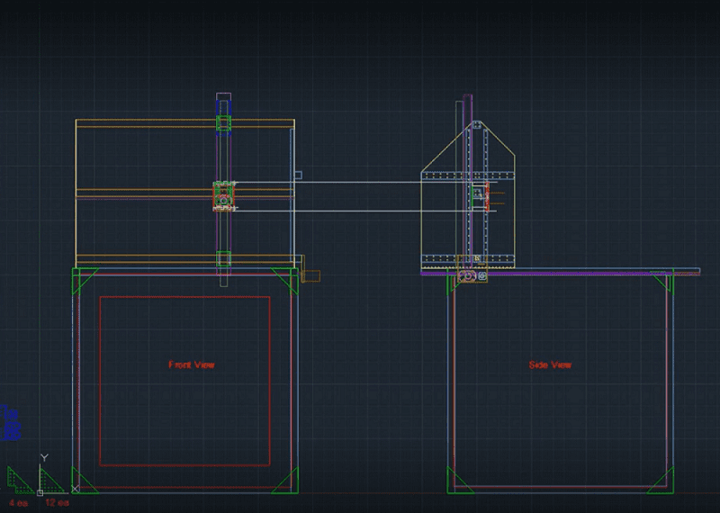
So this is my basic plan, I am trying for something that has a 4ft. x 4ft. x 4ft. envelope. The hope is that if I want to print a Wookiee I can cut him in half and print one half on top and then print the bottom half, so I can have an 8 ft. tall Wookiee. I’m not a big Star Wars fan but you never know when you might need a Wookiee!
The goal here was to use the cheapest software and hardware that I could get away with ‘cuz I’m cheap! But I also wanted something nice enough so that if you guys wanted to build it you could get the plans from me and they can happen. I think we have probably hit that, and by the time I finish this I can put together a very nice packet for everyone to follow along, but this is where it started.
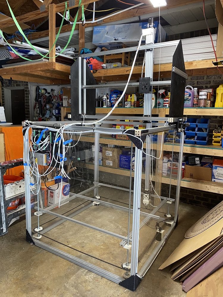
I’m planning to have a square box with plexiglass running all the way across to give me my squareness. So every side will have plexiglass except the front which will just have a frame. This is my Z-axis and I expect it to travel the entire depth of the 4ft. At the bottom of the Z-axis I’ll have an A and B axis for my 4th and 5th axis so it can spin and rotate. I’m using my own sheet metal because everything I found that was prebuilt was not as rigid as I wanted it to be.
I have 19 custom parts that had to be built. I probably could have 3D printed some of this stuff, but I didn’t know that at the time. Forgive me – it’s all a learning experience!
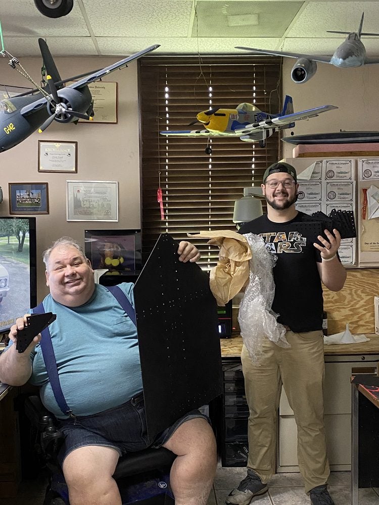
So these are the first parts coming in, with my nephew helping me unpack the parts. We were real excited to get our hands on this sheet metal!
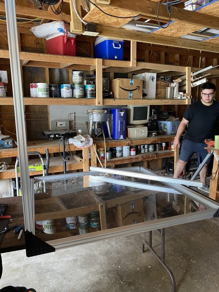
You’ll see there’s a piece of plexiglass in the middle and we are starting to build our parts. All of the sheet metal fit besides some gears that were not the right size so I had to make a few adjustments. Other than that, everything went exactly as planned.
Here you can see where we put our Y-axis, which will travel along a rail, and the Z-axis is sitting on the table.
We had to take this apart a couple of times because even though everything fit, the assembly order wasn’t quite as straightforward as I thought it would be. So we had to do some things in a certain order and I didn’t have that in mind when we were putting it together.
Of course, there were 3 years between the time I drew it up to when we actually put it together, so I forgot some things.
This little guy is 3D-printed because I didn’t have the gear I needed when I was building the metal parts. But this is going to be part of the mechanism that pulls the table up and down with my 6th axis. So it is a 5-axis router, but it has a 6th servo just to move the table that holds the working surface up and down – depending on the size of my project. If I have a smaller project then I would rather move it up close to the structure that is doing the milling so we have as little deviation as possible.
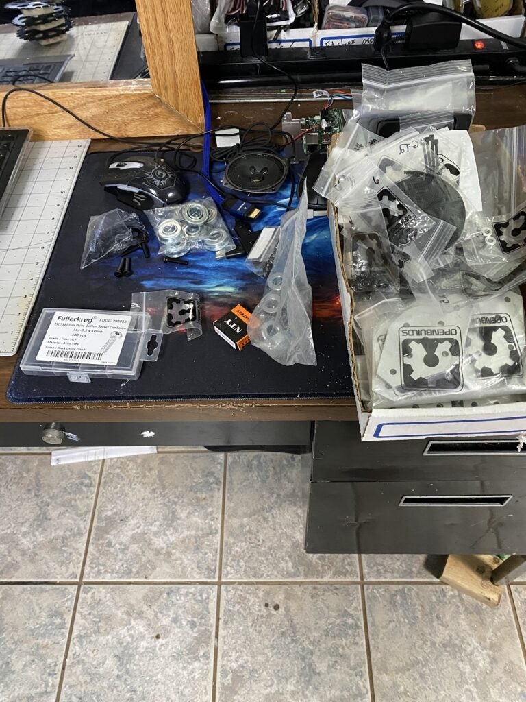
I had about 3 bins this size of hardware pieces that I bought that we didn’t end up using. Some of this is because I bought brackets of different sizes thinking they would help me with some things, but ended up making custom brackets instead. The bearings here were used as part of the lifting mechanism of the table.
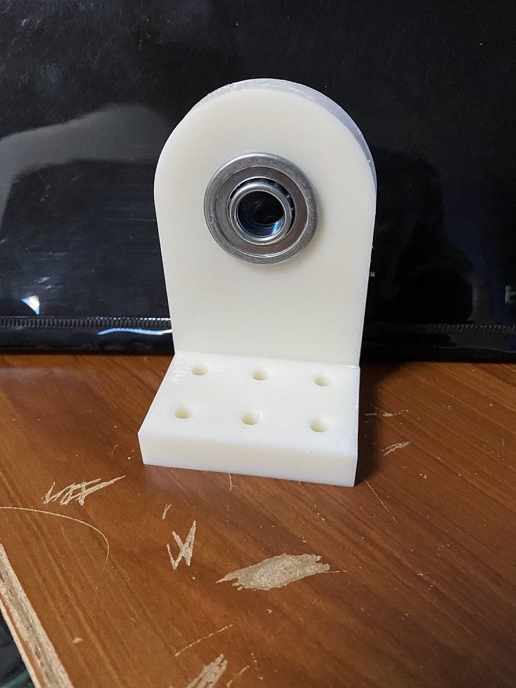
This was part of the lifting mechanism with the bearing. It was designed to hold that bearing straight out, so the rod going through it would always be at a precise angle.
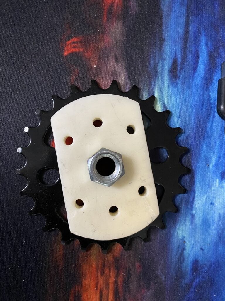
Here you see that little bracket with a threaded metal rod in the bottom corners. I have that spur gear from the bicycle. This spur gear will never change altitude, but it will spin the rod, and as the rod spins this piece will travel up and down. This bicycle chain I have will always keep all 4 edges of my table at the exact same height.
There’s my big servo on the right side, I got a pretty big one so that it would be able to lift a reasonable amount of weight. I did have to build a 3D printed bracket for that as well.
I also found that the metal at the ends of these was just to sharp and hard to deburr, so I 3D printed some end caps so no one would get hurt.
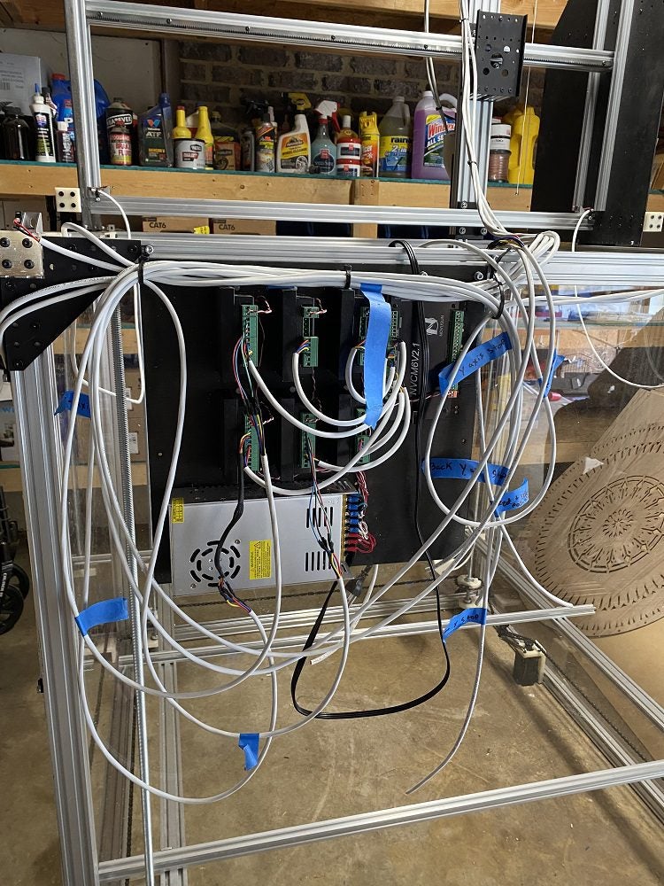
Here I got my control board. I have the actual modules that power the servos mounted on. I will have another 4 like this mounted to run the power supply that will power the build. It will run up and down that Z-axis.
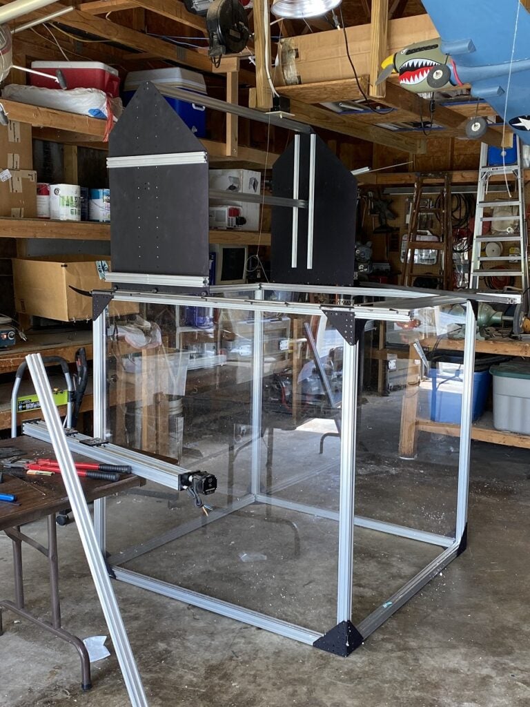
It’s hard to see, but in the back right you can see the 4th and 5th axis. It has quite a reach!
Now I am still testing everything, we have not run it in that frame yet, but that’s what we have so far. When I have everything done I would love to show some demos.
If you have any questions feel free to reach out to me with them, I would be happy to help!
Thank you for joining us for another Frank’s Garage Quick Bite. We hope this inspired you to create some beautiful pieces of your own. If you’re looking for more project ideas click the link below.
We would love to see your finished projects, send pictures or videos to the email below to be featured on Ultra Librarian.


")