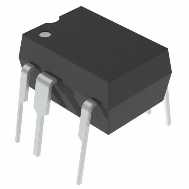
TNY277PN Eco-smart offline switcher
Among the many skills that engineers and PCB designers should continually strive to improve is how effectively they incorporate important knowledge and data into their workflow. This is not a trivial pursuit. In fact, navigating among the sheer number of competing sources can itself be a daunting and time-consuming exercise. Yet, there are tried and true resources; such as a resilient, comprehensive, and scalable online component library, that can aid you in optimizing your PCBA design process.
The need for accurate CAD models and data applies to every design. However, when there are several competing alternatives, which is the case for common circuit board functions like monitoring and control for power supplies, the depth of information and specificity of a component datasheet is unparalleled. An example is the TNY277PN datasheet, which describes a series of power supply switcher options.
TNY277PN: Features and Applications
The TNY277PN is an efficient solution for your electronic energy applications. The device is designed to provide reliable and safe switching for power supply monitoring and control. Notable features for the component include the following:
TNY277PN Features
- Current limit selection
- ON/OFF control without loop compensation need
- Self-biasing
- Low EMI, quiet source pins
- Automatic thermal recovery
- Automatic restart with less than 3% max power for short and open fault conditions
- No overshoot transient response
- Creepage extension between drain and other component pins
- Global energy efficiency regulation adherence
- Optional overvoltage shutdown and undervoltage threshold detect setting
These features enable the switcher circuit to be used in many applications, as shown below.
Common Applications for the TNY277PN
- Portable devices
- Digital cameras
- Cell phone chargers
- Cell phone adapters
- PDAs
- Portable audio players, MP3
- Shavers
- Low power decoders
- Portable video recorders (PVRs)
- DVDs
- Power supplies
- Appliances
- Industrial systems
- Metering devices
The features and applications above are not unique to the TNY277PN. The component is one of a series of similar switchers from Power Integrations Incorporated,
Alternative Components
As indicated in the TNY277PN datasheet, the TNY277PN is one of several alternatives as shown below.
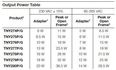
TinySwitch®-III series of switchers
As shown above, the features of the TinySwitch®-III series switchers can be utilized in many applications, based on specific power requirements. Additionally, each alternative component comes in a DIP-8 and SMD-8 package option.
TNY277PN: Architecture and Operation
Internally, the TNY277PN includes the functions shown in the diagram below.
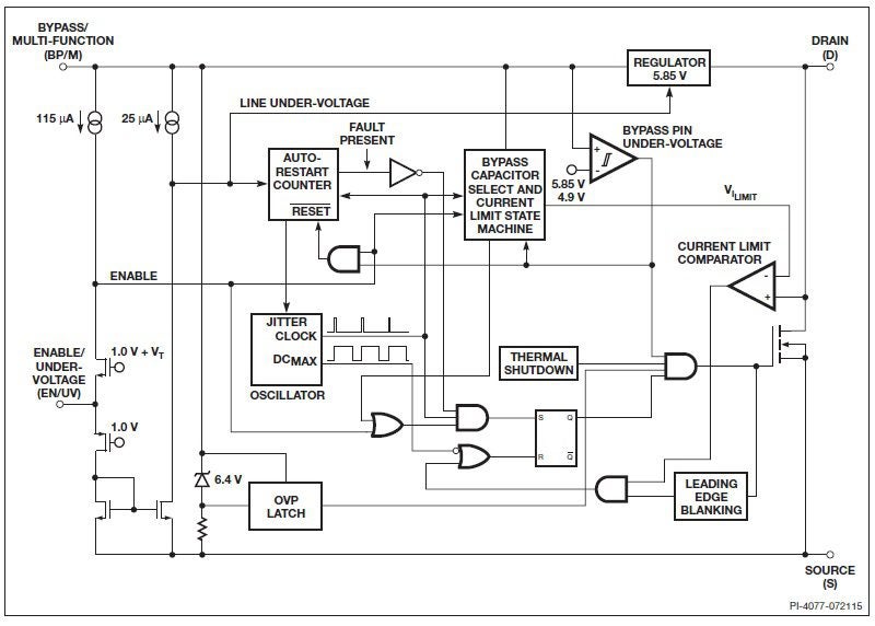
Operational diagram of the TNY277PN
Operationally, the switcher includes an oscillator that produces the clock and maximum duty cycle. The normal frequency is 132 kHz. Frequency jitter is incorporated to aid with EMI reduction. minimize EMI.
The device includes a state machine to limit current and enable the input. This pin controls the operation of a power MOSFET. If pin output current is above the threshold level of 115 µA, the MOSFET is turned ON at the beginning of each clock cycle. Otherwise, it remains OFF.
TNY277PN: Pins and Descriptions
Other important functions are best understood by analyzing the TNY277PN pins.
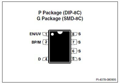
Pin configuration for the TNY277PN
TNY277PN Pin Descriptions
- EN/UV – Enable/Undervoltage
This pin controls the input and undervoltage response. While current remains below the threshold, the device is in normal operation mode. When the current rises above this threshold, the power MOSFET stood switching. This pin is also the source for undervoltage operation and determination. A DC line voltage connected through an external resistor is the source for undervoltage detection. Without this external circuit, no undervoltage detection is in effect.
- BP/M -Bypass/Multi-function
This pin provides multiple functions: Provides shutdown when current increases above a set value, connects an external bypass capacitor to the internal generated 5.85 V supply, and identifies the mode of operation. For example, connecting a 10 µF capacitor changes the limiting current to the rating of the next higher device in the series (TNY277 to TNY278).
- D – Drain
The drain pin is the source for steady-state and startup current.
- S – Source
The source may be connected at several points on the package, as shown on the pinout. Internally, this pin connects to the MOSFET output.
TNY277PN: Characteristics and Specifications
When designing with the TNY277PN–or one of the alternatives–it is important to know the device attributes. Important parameters are the maximum ratings, electrical and thermal characteristics, and constraints. These are illustrated in the figures below.
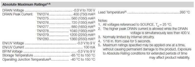
Absolute maximums for the TNY277PN
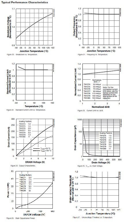
Typical characteristics for the TNY277PN
PCBA Design With the TNY277PN Datasheet
Although, this switcher can be utilized in many different configurations, the TNY277PN datasheet provides you with a suggested layout design.
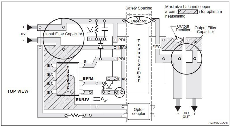
Recommended TNY277PN layout design
The datasheet also includes a quick checklist that should be helpful for design efficiency.
In order to make use of the design information and tips from the TNY277PN datasheet, it is first important to ensure that your component CAD model and data is accurate, and from a trusted database, as is the schematic, footprint and 3D model below.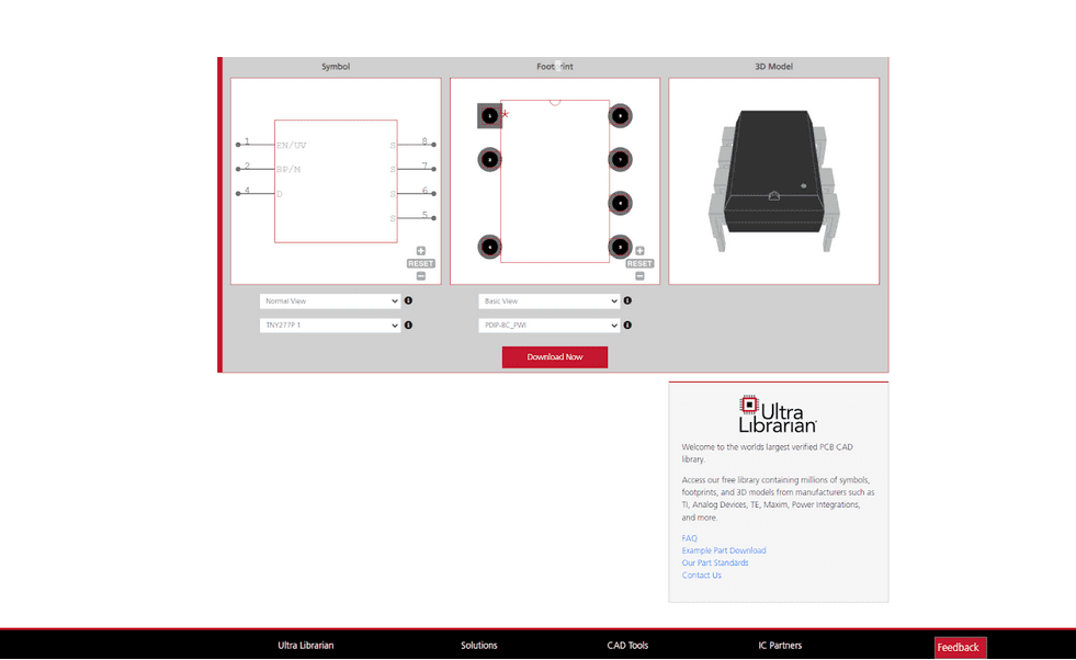 TNY277PN CAD data from UL
An effective online database is not only important, it is sometimes critical. For example, when finding an obsolete part model and/or data is required. By coupling this PCB layout data with the specific characteristics, specifications and performance metrics, typically only available in a datasheet, you are equipped with the essential component resources for your design.If you’re looking for CAD models for common components and design information like how to best use the TNY277PN datasheet for your PCBA design, Ultra Librarian helps by compiling all your sourcing and CAD information in one place.
Working with Ultra Librarian sets up your team for success to ensure streamlined and error-free design, production, and sourcing. Register today for free.


")