While writing drivers for chips, when you use microcontrollers, you deal with an extra board that is part of the interface. There is a chance that the microcontroller can crash or brownout because of power. However, this problem ceases to exist with a USB to I2C/UART adapter like the MCP2221A. All you have to do is to plug the device into the computer, connect the sensor and start writing the driver without getting worried about a middle controller.
The MCP2221A is a USB interface chip that can convert USB protocol to legacy serial and I2C. Moreover, it has four general-purpose input-output pins (GPIO). GPIO pins can be used as Digital i/p and o/p, Analog i/p and o/p, or to generate PWM signals. Thus, it saves you the hassle of buying and programming microcontrollers to interface these functionalities with your computer. Understanding the MCP2221A datasheet helps you reap all the benefits of this chip within its maximum limits.
MCP2221A – Features, Specifications, and Applications
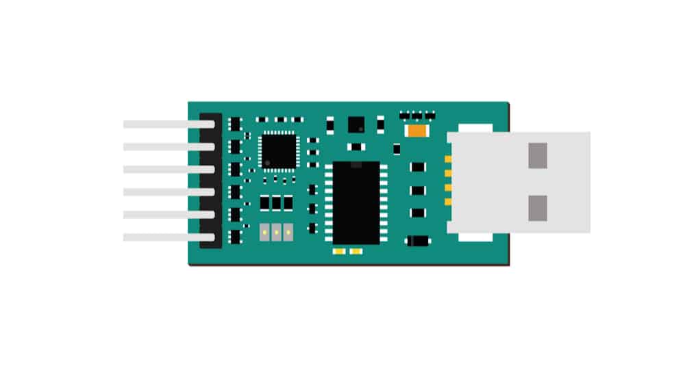
The MCP2221A is a low-cost and easy-to-use USB to I2C/UART adapter. Here, no soldering is required because you can plug it into the system at one end and connect it to the sensor at the other end.
You can also use it with grove sensors. It has a UART, so it also comes with a full Rx, Tx UART. Thus, you can use it for devices like GPS and some particle sensors. Designers can refer to the MCP2221A datasheet for more details on the sub-command structure for the UART function.
Features
- USB to UART/I2C conversions
- I2C device control and configuration
- UART Tx and Rx signals
- Support Baud Rates 300-468000
- Four GPIO pins
- External interrupt edge detection
- Electrostatic discharge protection
- Automotive AEC-Q100 qualified
Specifications
- Power supply voltage: 5V/3.3 V
- ADC resolution: 10 bits 3 channels (multiplexed)
- ADC sampling rate: 1 KSPS
- DAC resolution: 5 bits 2 channels (multiplexed)
- I2C maximum speed: 400 kHz
- Max Baud rate: 460800
- USB support: low speed (1.5 Mbps) and full-speed (12 Mbps)
Applications
- Microcontroller to PC interfacing
- Digital and Analog sensor interface to PC
- Handheld devices with a USB interface
- Actuator and motor computer control
- Barcode readers
Understanding MCP2221A Datasheet
Package and Pin Layout
Unlike other USB interface chips that come only in the SMT package, MCP2221A comes in a PDIP package that offers ease of use while connecting the circuits on the board. The PDIP package makes it good to go without any surface mount adaptors, as with other interface chips from FTDI and Texas Instruments.
MCP2221A is available in the following packages:
- 14-Lead PDIP
- 14-lead SOIC
- 14-lead TSSOP
- 14-lead QFN
The MCP2221A is a USB to UART serial converter that helps you connect devices with UART and I2C bus directly to your computer without any external components. Pinout descriptions for the model are as follows.
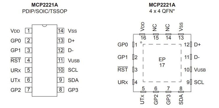
As you can see, Pin 1 and Pin 14 represent the power supply and the ground, respectively. The chip can directly receive power from the USB. There are four dedicated GPIO pins- 2,3, 7, and 8.
For the ADC channel, pins 3,7,8 can be used, whereas pins 7 and 8 are connected to the DAC channel.
This chip can work as SMBus (System Management Bus) or PMBus (Power Management Bus) and is mostly used for temperature control and monitoring for processors and low-speed peripherals on motherboards.
Pin 11 can be used as a USB voltage regulator that can output 3.3 volts. If unused, the pin should be grounded with a 470 nF capacitor. For more details, designers should refer to the “DC Characteristics” from the MCP2221A datasheet.
Building Block
The below figure shows the circuit diagram for the MCP2221A chip.
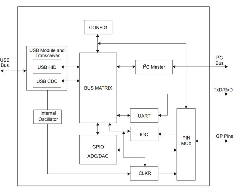
It is easy to acknowledge from the circuit diagram that the chip requires only an external pullup resistor and a 470 nanofarads capacitor for setup. The capacitor will connect to the VUSB pin, and the resistor will go to the RST pin.
The bus matrix is the main part of the device to which all rest modules are tied and controlled, including UART, GPIO, ADC, DAC, and clock output.
Improved Baud Rates
The predecessor of the device, the MCP2221 had a baud rate of 1,15,200. However, MCP2221A can support a baud rate up to 4,60,800. The manufacturer has provided certain preconfigured primary baud rate settings, along with the associated rounding errors as follows.
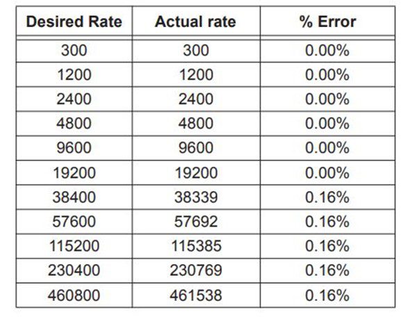
It is also possible to achieve customized baud rates using the SET-LINE-CODING command, but the percentage of error will fluctuate as well.
Designing a board with MCP2221A requires a clear understanding of the MCP2221A datasheet, footprints, and sourcing data. Ultra Librarian offers a comprehensive online resource to fetch PCB footprints, technical data, and 3D CAD models with ease.
Working with Ultra Librarian sets up your team for success to ensure streamlined and error-free design, production, and sourcing. Register today for free.


")