
IR2110 pinout in PDIP IC architecture
The days when you could fix pretty much everything on your car in the backyard with a modest assortment of screwdrivers and sockets are a distant memory. Vehicles today may contain as many as a few thousand microchips. These components enable the design of automotive systems with ever increasing functionality that translates into more comfortable, reliable, and safer transportation for drivers and passengers.
Many of the ICs in automotive systems are transistors; including MOSFETs and insulated-gate bipolar transistors (IBGTs). An important aspect of employing these devices is the driving circuitry. An integrated monolithic HVIC driver for high-speed, high-voltage, dual-channel operation that has proven to be very successful for automotive applications is the IR2110. By examining the IR2110 pinout and component characteristics you will be able to best use this IC module in your design.
The IR2110 Pinout
The IR2110, manufactured by Infineon Technologies comes in two common IC package options: plastic dual in-line package (PDIP) and small outline integrated circuit (SOIC) package. The IR2110 pinouts for these package types, are shown below.
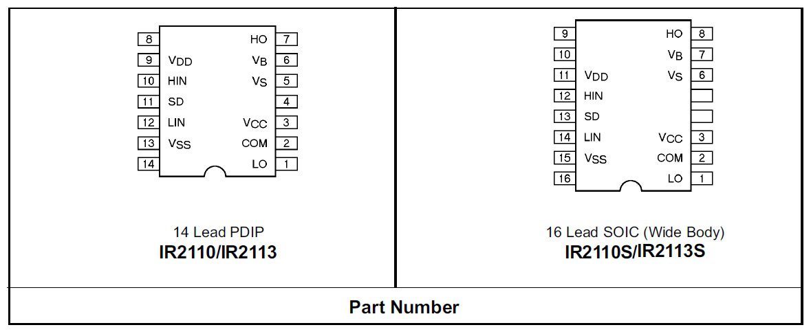
IR2113 and IR2110 pinouts for PDIP and SOIC packages
As indicated above, the IR2113, which is a faster switching device for higher voltage applications, has the same pin designations as the IR2110. From the IR2110 datasheet, the pin descriptions are listed in the table below for both package types.
As listed, both devices have both a low and high side input and output. For the IR2110, the high side max voltage is 500V. For the IR2113, this voltage is 600V. These and other important features are given in the section below.
IR2110 Component Architecture and Parameters
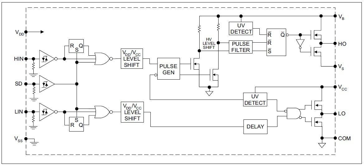
Block diagram of the IR2110 gate driver circuit
The diagram above, provides a block diagram perspective of the IR2210. As shown, the high and low sides are independent of each other. Cross conduction is minimized by the high power current buffer stage. These and other features of the component are below.
Features and Applications of the IR2110
The primary features of the IR2110 are:
These attributes and capabilities make the IR2110 a great option for:
Applications for the IR2110
- Automotive power distribution, ADAS domain controller
- Industrial drives, robotics
- Space and satellite communications systems
- Mobile and IoT security systems
- Battery Management Systems (BMSs)
- Motor drives
- Power tools
- Wearables
Obviously, there are a large number of applications for which the IR2110 is a good fit. This application flexibility is possible due to the component characteristics and specifications below.
Characteristics and Specifications
When utilizing the IR2110 (and IR2113), the following restrictions apply.
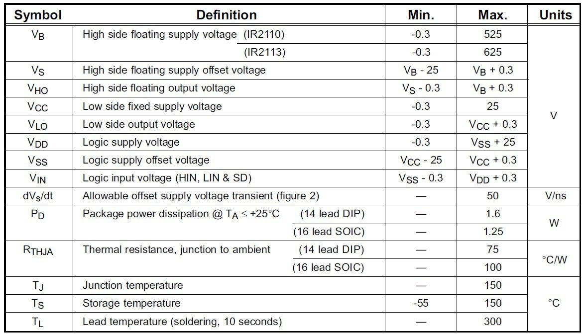
Absolute Maximum Ratings
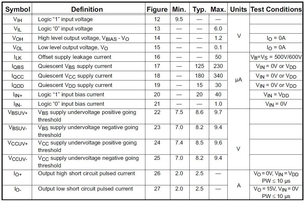
Static electrical characteristics of the IR2110
Other important characteristics to ensure accurate timing and synchronization are:
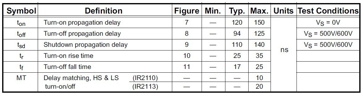
Dynamic electrical characteristics of the IR2110
PCBA Design With the IR2110 Gate Driver
Although, there are various design configurations options available to you, typically the IR2110 is implemented as shown below.
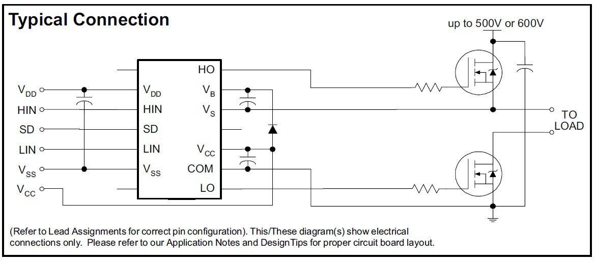
Typical circuit configuration for the IR2110
As the IR2110 pinout, and other specifications described above indicate, this MOSFET and IGBT driver can be used for various applications across many industries. Irrespective of the deployment, it is essential that accurate, manufacturer vetted CAD data, as shown below, be used. Doing so, will aid your development process and help your CM build reliable PCBAs for your project.
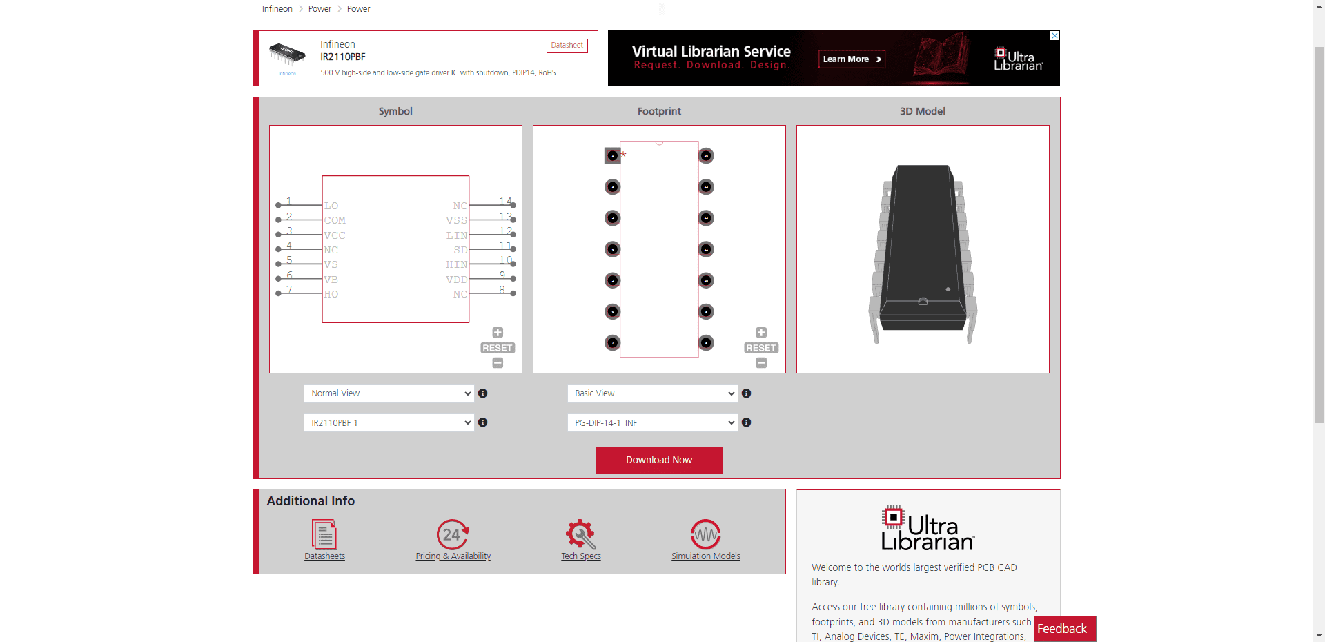
IR2110 PDIP CAD models from UL
If you’re looking for CAD models for common components and/or important design information like analysis of the IR2110 pinout, Ultra Librarian helps by compiling all your sourcing and CAD information in one place.
Working with Ultra Librarian sets up your team for success to ensure streamlined and error-free design, production, and sourcing. Register today for free.


")