The INA121P low power instrumentation amplifier
You probably know that people are living longer today than their ancestors of a few short generations ago did. However, you may not realize that in the US, life expectancy rates are about 40% longer today than in 1860. Why such a tremendous change?
Better understanding of our physiology, increasingly higher skilled health professionals, medical discoveries like penicillin, and widespread use of vaccines undoubtedly have contributed. However, the role of technology, especially medical devices driven by electronics, cannot be overstated. From simple monitoring devices, like thermometers, to life-sustaining systems, like pacemakers, electronic medical devices help us live longer and more active lives.
Medical devices often capture and process biological data. A common example is an electrocardiogram (ECG), which receives low-power electrical signals that provide information about patient heart rate and rhythm. To be used by medical professionals, this data must be analyzed, which includes processing by a low noise amplifier designed for biomedical applications. A popular component that meets these qualifications is described in detail in the INA121P datasheet.
INA121P: Applications and Features
The INA121P, which is a low power, field-effect transistor (FET)-input amplifier, has been a popular choice for PCBA designers for decades. This component can be generally used for many design types. However, it’s features, as listed below, make this component especially useful as a driver of accurate health and medical application electronics.
INA121P: Architecture and Operation
From the INA121P datasheet, the functional diagram of the componet is shown below.
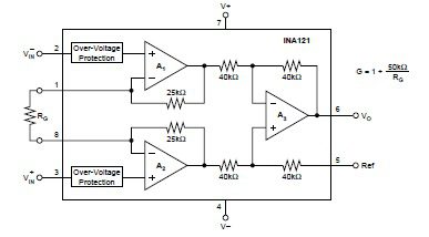
INA121P functional diagram
Notably, the INA121P is comprised of three operational amplifiers, which accentuates its versatile operation. Dual packaging options also support flexible mounting–for example, the through-hole option is better suited for industrial environments where motion may be a significant concern. For both cases, the device pinout is as shown below.
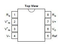
INA121P pinout
As the pinout indicates, the INA121P requires biasing for the internal opamps (pins 4 and 7). There are also two inputs (pins 2 and 3) and one output (pin 6, for which pin 5 serves as the reference). The gain of the device, which can range from 1 V upto 10 kV/V, is set by the choice for RG (pins 1 and 8).
INA121P: Important Electrical and Thermal Specifications
The INA121P datasheet includes important parametric data and specifications to ensure proper operation of the amplifier. Most important is to ensure that the component is not exposed to electrical and/or thermal conditions that fall outside of the constraint ranges below.
ABSOLUTE MAXIMUM RATINGS FOR THE INA121P
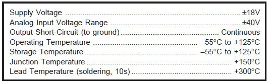
INA121P maximum ratings
The environmental conditions above allow the INA121P to be safely utilized in sensitive medical systems as well as harsh industrial situations. Other important parameters and specifications to guide your design are listed below.
OPERATIONAL SPECIFICATIONS FOR THE INA121P
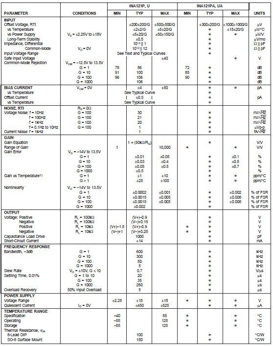
INA121P parameters and specifications
INA121P PCBA Design Essentials
The INA121P is a very versatile amplifier circuit. However, for reliable operation and performance there are essentials that must be adhered to. Among these are ensuring an internal return path for bias current. There are several ways, as shown in the figure below, this critical operational factor can be accomodated.
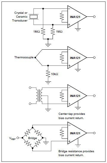
Suggested circuits for common mode current
Failing to stabilize common mode current can have a significant adverse effect on the ability of the INA121P to function properly. It may also be advisable to opt for an alternative component for cases where the input source impedance is low. Choices include the the INA103 if input impedance is ≤ 1kΩ. Irrespective of your component choice, it is imperative that you employ accurate CAD data and models from a reliable source, as illustrated below.
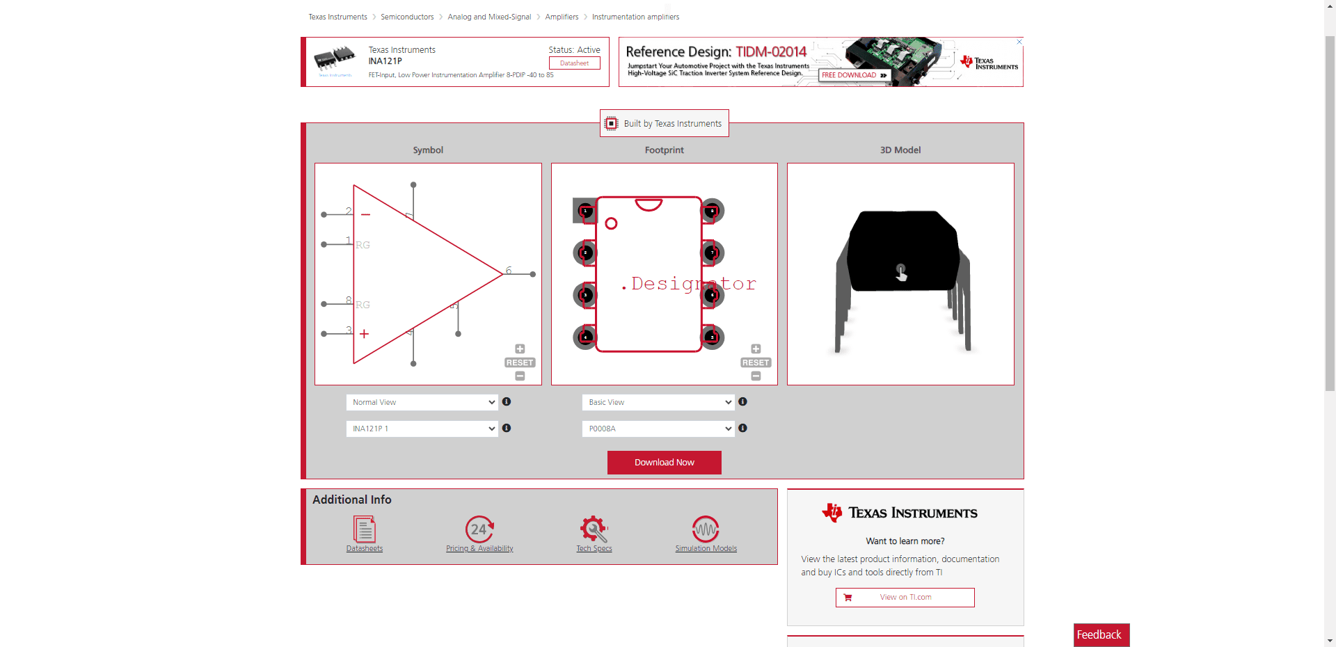
INA121P schematic symbol, footprint, and 3D CAD model from UL
If you’re looking for CAD models for common components or important information, like how to best use the INA121P datasheet for your design, Ultra Librarian helps by compiling all your sourcing and CAD information in one place.
Working with Ultra Librarian sets up your team for success to ensure streamlined and error-free design, production, and sourcing. Register today for free.