MOSFET thermal analysis of Toshiba’s TPH12008NH MOSFET with simplified CFD model
Computational fluid dynamics or CFD, which is a branch of study where statistical analysis methods are used to study fluid flow, is probably most often thought of as being a tool for designing aerospace, automotive, marine, and other large system-level structural surfaces. However, CFD techniques are also used to analyze fluid flow, which includes gases, internally. This includes assessing how heat is distributed and dissipated from electronic components and circuit boards.
Avoiding the damages to parts, traces, and PCBAs that can result from overheating necessitates that effective thermal analysis be a major consideration of your design process. This is especially true for processors, FPGAs, converters, or other devices that are comprised of active components like MOSFETs and/or drivers, are included on your board. To help address this issue, electronics industry innovator, Toshiba Electronic Devices & Storage Corporation, has developed simplified CFD models for cooling simulation focusing on MOSFET.
Simplified CFD Model Design
CFD modeling can be quite complicated. For example, there are mesh models that employ complex algorithms like Delaunay triangulation to develop geometrical models for analyzing fluid flow at the boundary of a surface. The Toshiba simplified CFD model is intended to release engineers from the task of model specification often needed to obtain accurate fluid slow results.
Model Architecture
As shown below, the simplified CFD model consists of only five elements to represent the thermal activity of the component under evaluation.
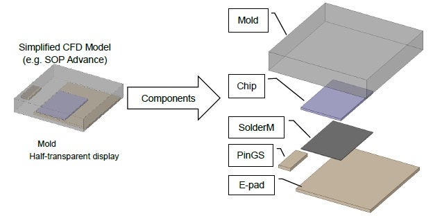
Component structure of the simplified CFD model
This architecture greatly simplifies defining a suitable CFD model for cooling simulation analysis an example of which is described below.
How to Use Toshiba’s CFD Model
In order to implement Toshiba’s simplified CFD model, it is necessary to specify parameters for the components of the structure. These include thermal conductivity, specific heat, and density, as shown below.
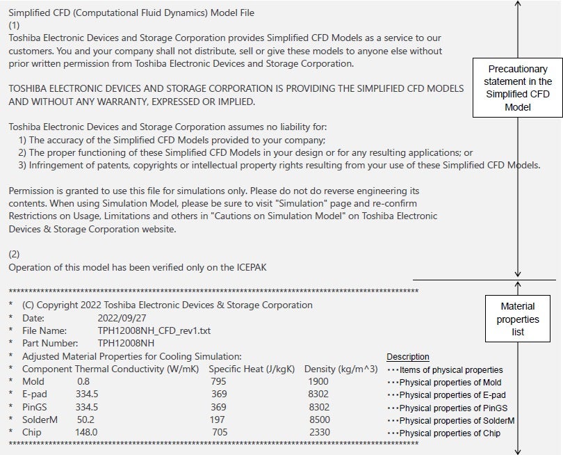
Component parameter specifications for Toshiba’s simplified CFD model
The model specifications above are provided in the standard STEP file format. An example of how to use the model is provided below.
MOSFET Thermal Analysis Example
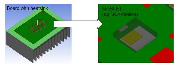
3D CAD view of simplified CFD model
As shown above, it is necessary to convert the model into the CAD file format required by your CFD solver. In this case, the 3D geometrical model allows for evaluation of thermal flow in all directions.
Simulations and Results
For this example, the TPH12008NH MOSFET was used. Six semiconductors arranged atop a heatsink, as shown in the Overall view below, were evaluated. The analysis method was a cooling simulation and results were obtained of heat flows both internal and external to the semiconductor.
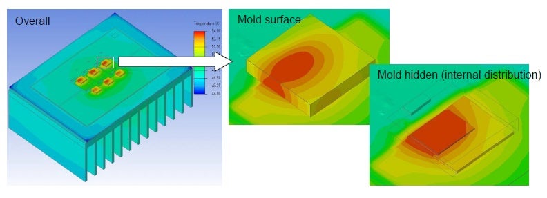
Heat distribution views of the semiconductor interior and exterior
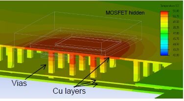
Below, an exploded view of the MOSFET is shown, which illustrates the heat distribution along vias connected to the drain.
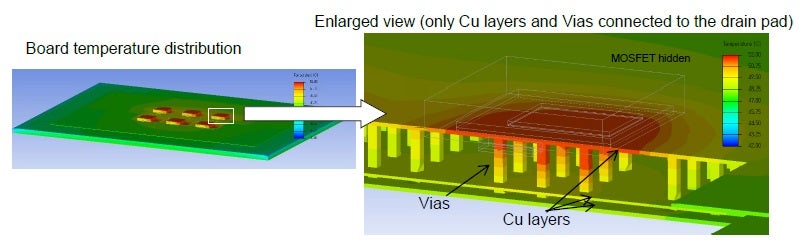 Board surface and via distribution views
A view of heat flow through the heatsink is also available, as shown below.
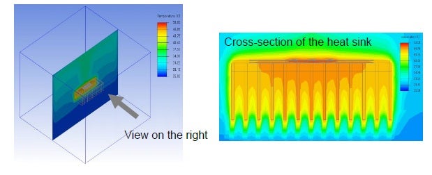
Heatsink distribution view
The views above provide the thermal information necessary to evaluate a component’s ability to disseminate heat and maintain operation, as well as heatsink effectiveness.
Additional Views
For this cooling simulation, the CFD solver provides additional views of heat flow and flow velocity. These are illustrated below.
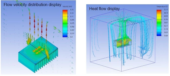
Views of velocity and heat flow
The wealth of information obtained directly and that can be derived from the thermal simulations; such as the example above, is substantial. And provides PCBA designers and engineers with accurate data that enables the optimization of their design for thermal distribution and dissipation. This coupled with the advantage of an uncomplicated simple CFD model can greatly aid design and development optimization.
All images in this article are provided by Toshiba Electronic Devices & Storage Corporation.
If you’re looking for CAD models for common components or information on innovations like Toshiba’s simplified CFD model, Ultra Librarian helps by compiling all your sourcing and CAD information in one place.
Working with Ultra Librarian sets up your team for success to ensure streamlined and error-free design, production, and sourcing. Register today for free.