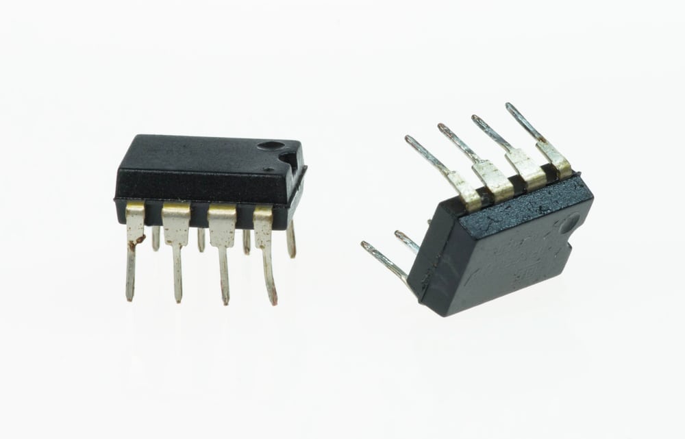
Operational amplifiers are a type of low voltage amplifier.
Low voltage amplifier circuits amplify weak input signals for further processing or transmission. These circuits are often used in audio applications, sensor interfaces, and communications systems with weak input signals. The table below summarizes the common low voltage amplifier types and their characteristics.
Based on circuit configurations and component values, actual performance may differ from this table. The choice of amplifier type depends on the application requirements, such as gain, input/output impedance, frequency response, and other factors.
Designing a Low Voltage Amplifier Circuit
Designing a low voltage amplifier circuit involves several considerations, including amplifier type, component selection, gain requirements, input/output impedance matching, power supply constraints, and board compatibility. A general guideline for designing a low voltage amplifier circuit follows:
1. Amplifier Type Selection
- Select an amplifier type suitable for your application, such as op-amps, transistor-based amplifiers (common emitter, common collector, common base), Darlington pairs, cascode amplifiers, etc.
- Balance the trade-offs between gain, input/output impedance, bandwidth, and power consumption.
2. Gain and Frequency Response Setting
- Determine the required gain for your application.
- Define the frequency range of the signals you want to amplify
- Design the circuit for the appropriate bandwidth.
3. Component Selection
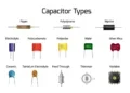
- Select resistors and capacitors to set the desired gain and frequency response.
Pay attention to tolerance and temperature coefficients. - Choose transistors or op-amps with low noise characteristics, especially if amplifying small signals.
- Ensure the selected components can operate within the specified low voltage range.
4. Power Supply Requirements
- Determine the minimum and maximum power supply voltage requirements for your amplifier circuit.
- Use voltage or low-dropout regulators to ensure a stable and clean power supply.
- Consider the power consumption of the amplifier, especially in battery-powered applications.
5. Input and Output Impedance Matching
- Match the amplifier’s input impedance to the source impedance to avoid signal loss.
- Harmonize the amplifier’s output impedance to the load impedance for efficient power transfer.
6. Signal Conditioning and Filtering
- Use input protection, filtering, and conditioning components to amplify only the desired signals.
- Include coupling capacitors to block DC components and biasing networks if needed.
7. Board Layout and Grounding
- Pay attention to the layout to minimize parasitic capacitance, inductance, and interference.
- Implement proper grounding to minimize noise.
- Keep high-current and low-current ground paths separate.
8. Testing and Simulation
- Verify the circuit’s performance with simulation tools.
- Prototype the circuit on a breadboard and perform thorough testing to ensure it meets the specifications.
9. Component Integration
- Ensure that the amplifier circuit interfaces correctly with other components on the board, such as microcontrollers, sensors, or other signal processing elements.
- Consider the overall system requirements and compatibility.
10. Documentation
- Document the circuit design, including component values, connections, and design considerations.
- Keep a record of test results and modifications made during the testing phase.
Follow these steps to design a low voltage amplifier circuit that meets the specific requirements of your application and ensures compatibility with other components. It is essential to iterate through the design, testing, and refinement phases to achieve the desired performance.
Optimizing Your Low Voltage Amplifier Design
Your ability to optimize your low voltage amplifier circuit design depends upon the accuracy of your active component library. To ensure your component symbol, footprint, and 3D model are correct, you should turn to a trusted resource like Ultra Librarian so there will be a match with the manufacturer’s data files.
If you’re looking for CAD models for common components or low voltage amplifier circuits, Ultra Librarian helps by compiling all your sourcing and CAD information in one place.
Working with Ultra Librarian sets up your team for success to ensure streamlined and error-free design, production, and sourcing. Register today for free.


")